2019 FORD F-150 lock
[x] Cancel search: lockPage 271 of 644

Zone coverage also decreases when
parking at narrow angles. The sensor on
the left-hand side is mostly obstructed and
zone coverage on that side is severely
reduced.
System Lights, Messages and
Audible Alerts
When the system detects a vehicle, an
indicator illuminates in the exterior mirror
on the side the approaching vehicle is
coming from. A tone sounds and a
message appears in the information
display.
Note:
In exceptional conditions, the system
could alert you even when there is nothing
in the detection zone, for example a vehicle
passing in the distance.
Blocked Sensors The sensors are inside the brake lamp on
both sides of your vehicle.
Note:
Keep the sensors free from snow, ice
and large accumulations of dirt.
Note: Do not cover the sensors with bumper
stickers, repair compound or other objects.
Note: Blocked sensors could affect system
performance.
If the sensors are blocked, a message may
appear in the information display when
you shift into reverse (R). See
Information Messages (page 128).
System Limitations
The system may not correctly operate
when any of the following occur:
• The sensors are blocked.
• Adjacently parked vehicles or objects
are obstructing the sensors.
• Vehicles approach at speeds greater
than
37 mph (60 km/h).
• The vehicle speed is greater than 7 mph
(12 km/h)
.
• You reverse out of an angled parking
space.
System Errors
If the system detects a fault, a message
displays. See General Information (page
116
).
Switching the System Off and On
You can temporarily switch the system off
using the information display. See
General
Information (page 116). When you switch
the system off, a message displays.
See
Information Messages (page 128).
Note: The system turns on each time you
switch the ignition on and you shift into
reverse (R). If you temporarily switch the
system off, it turns on the next time you
switch the ignition on.
268
F-150 (TFC) Canada/United States of America, enUSA, Edition date: 201808, Third-Printing- Driving AidsE142442 E190708
Page 275 of 644

Note:
Distance Indication and Alert
deactivates and the graphics do not display
when Adaptive Cruise Control is active. Time Gap
Distance Gap
Graphics
Sensitivity
Speed
>0.9sec
>82 ft (25 m)
Grey
Normal
62 mph
(100 km/h)
0.6sec —0.9sec
56–82 ft
(17 –25 m)
Yellow
Normal
62 mph
(100 km/h)
<0.6sec
<
56 ft (17 m)
Red
Normal
62 mph
(100 km/h)
Adjusting the Pre-Collision Assist
Settings
You can adjust the following settings by
using the information display controls.
See
General Information (page 116).
• You can change Alert and Distance
Alert sensitivity to one of three possible
settings.
• You can switch Distance Indication and
Alert on or off.
• If required, you can switch Active
Braking on or off.
• If required, you can switch the entire
Pre-Collision Assist feature on or off.
Note: Active braking automatically turns
on every time you switch the ignition on.
Note: If your vehicle has a radar sensor, we
recommend that you switch the system off
if you install a snow plow or similar object
in such a way that it may block the radar
sensor. Your vehicle remembers the selected
setting across key cycles. Blocked Sensors
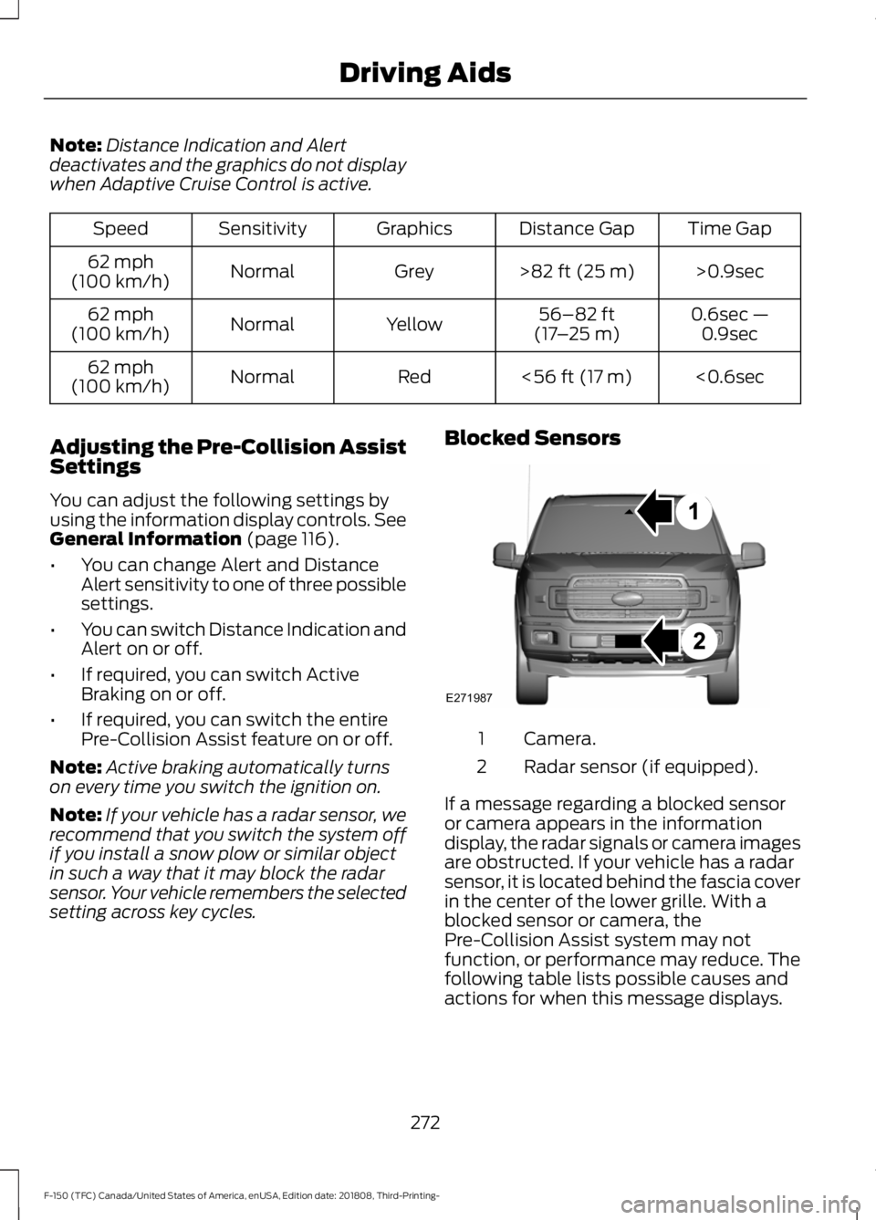
Camera.
1
Radar sensor (if equipped).
2
If a message regarding a blocked sensor
or camera appears in the information
display, the radar signals or camera images
are obstructed. If your vehicle has a radar
sensor, it is located behind the fascia cover
in the center of the lower grille. With a
blocked sensor or camera, the
Pre-Collision Assist system may not
function, or performance may reduce. The
following table lists possible causes and
actions for when this message displays.
272
F-150 (TFC) Canada/United States of America, enUSA, Edition date: 201808, Third-Printing- Driving AidsE271987
Page 279 of 644

LOAD RETAINING FIXTURES (IF
EQUIPPED)
BoxLink
™ Cleats
These cleats attach to the inner box walls
to help you to tie down cargo. The cleats
can be locked to prevent removal or
unlocked for removal.
BoxLink Cleats
Note: Leave the key in the lock when
removing or installing the cleats. The key
cannot be removed from the lock unless it
is in the locked position. A. 275 lb (1,223 N) maximum force
between directly opposed cleats.
B. 600 lb (2,669 N)
maximum force
between diagonally opposed cleats. Secure cargo with up to
275 lb (1,223 N)
force applied between opposing box link
cleats, or up to
600 lb (2,669 N) force
applied between diagonal box link cleats.
Removing Locking BoxLink Cleats
1. Insert the key into the lock and turn clockwise to unlock.
2. Pull bottom of the cleat outward while
pushing top of cleat down.
3. Hold on to the cleat as it clears the mounting slot.
Installing Locking BoxLink Cleats 1. Insert the key into lock and turn
clockwise to unlock.
2. Insert the cleat into the mounting slot and push upward. Make sure the cleat
is fully engaged.
276
F-150 (TFC) Canada/United States of America, enUSA, Edition date: 201808, Third-Printing- Load CarryingE184885 E189558
Page 280 of 644

3. Turn the key counterclockwise to lock.
4. Remove the key.
LOAD LIMIT
Vehicle Loading - with and
without a Trailer
This section guides you in the
proper loading of your vehicle,
trailer, or both. Keep your loaded
vehicle weight within its design
rating capability, with or without
a trailer. Properly loading your
vehicle provides maximum return
of vehicle design performance.
Before you load your vehicle,
become familiar with the
following terms for determining
your vehicle
’s weight rating, with
or without a trailer, from the
vehicle ’s Tire and Loading
Information label or Safety
Compliance Certification label. Tire and Loading Label Information
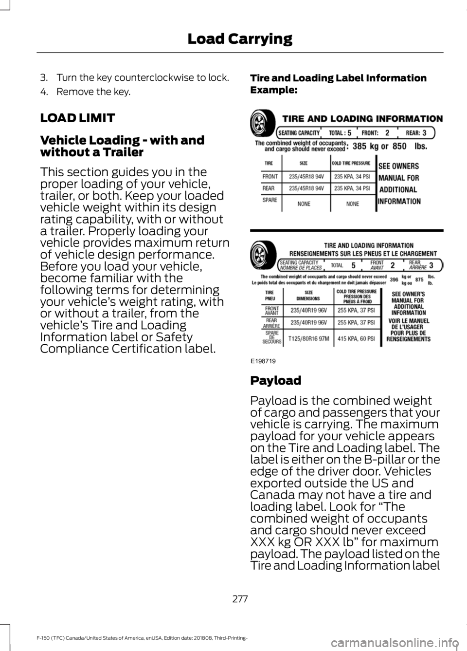
Example:
Payload
Payload is the combined weight
of cargo and passengers that your
vehicle is carrying. The maximum
payload for your vehicle appears
on the Tire and Loading label. The
label is either on the B-pillar or the
edge of the driver door. Vehicles
exported outside the US and
Canada may not have a tire and
loading label. Look for
“The
combined weight of occupants
and cargo should never exceed
XXX kg OR XXX lb ” for maximum
payload. The payload listed on the
Tire and Loading Information label
277
F-150 (TFC) Canada/United States of America, enUSA, Edition date: 201808, Third-Printing- Load CarryingE198719
Page 286 of 644

4. Rotate the stops at the underside of
the ramp to the open position.
Note: You can use a smooth surface tool
to rotate the stops. 5. Slide the ramp claw onto the tailgate
plate. 6. Pull the location pin outward and
extend the ramp until the pin is seated
in the usage position, then set the ramp
on even ground.
Stowing the Bed Ramp
1. Pick up the ramp. Pull the location pin outward.
2. Slide the ramp into the storage position
until the location pin locks.
Note: Make sure the proper pin location has
been applied for your bed size.
3. Slide the ramp claw off of the tailgate plate.
4. Rotate the stops at the underside of the ramp to the closed position.
283
F-150 (TFC) Canada/United States of America, enUSA, Edition date: 201808, Third-Printing- Load CarryingE211150 E194382 E194383
Page 287 of 644

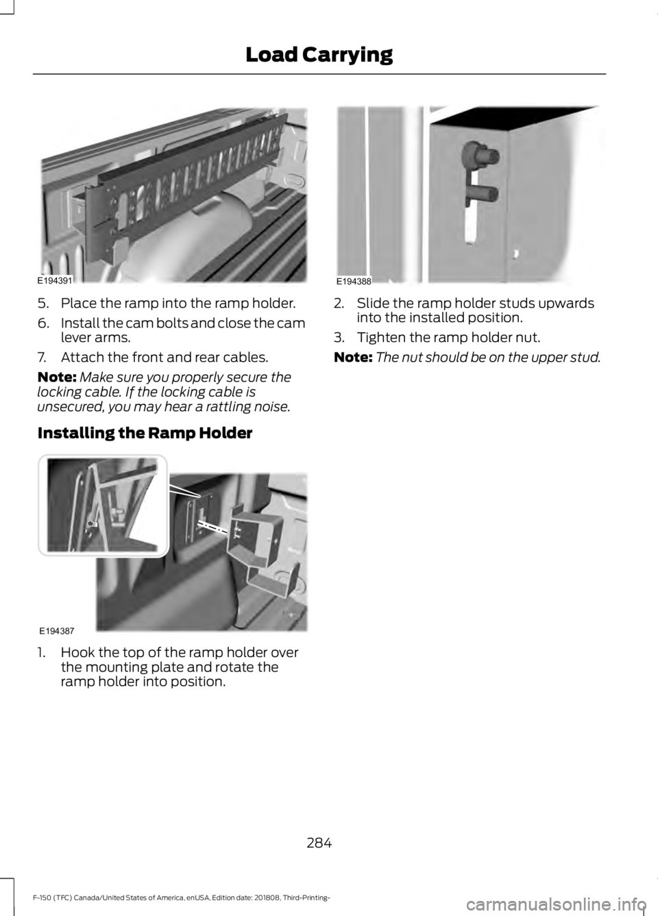
5. Place the ramp into the ramp holder.
6.
Install the cam bolts and close the cam
lever arms.
7. Attach the front and rear cables.
Note: Make sure you properly secure the
locking cable. If the locking cable is
unsecured, you may hear a rattling noise.
Installing the Ramp Holder 1. Hook the top of the ramp holder over
the mounting plate and rotate the
ramp holder into position. 2. Slide the ramp holder studs upwards
into the installed position.
3. Tighten the ramp holder nut.
Note: The nut should be on the upper stud.
284
F-150 (TFC) Canada/United States of America, enUSA, Edition date: 201808, Third-Printing- Load CarryingE194391 E194387 E194388
Page 295 of 644

Turn and hold counterclockwise to make
the trailer go left.
Turn and hold clockwise to make the trailer
go right.
Note:
Practice maneuvering with the
system in a safe open area first.
Note: Try backing up in a straight line and
then turning the knob slowly in the direction
you want to go.
Note: Quickly turning and releasing the
knob results in a jerky movement of the
vehicle. Release the knob when the trailer is
moving in the direction you want. Control
the accelerator and brakes while the
system steers your vehicle automatically
to keep the trailer moving straight back.
Note:
You may have to use the knob to
correct the trailer direction when attempting
to move the trailer straight back under some
conditions.
Note: The system limits the vehicle speed.
Note: When you release the knob or turn it
to the center position, your vehicle follows
the trailer's path.
Troubleshooting
Note: The system requires a clear view of
the sticker placed on the trailer. You must
keep the camera lens and sticker clean for
the system to operate correctly.
Setup
The system is designed to be used with a
wide variety of trailers. There are some
trailers that do not have a proper surface
and location to mount the sticker. These
trailers are not supported. Attempts to
place the sticker on a surface that does
not meet the sticker placement
requirement listed in Step 3 of the setup
instruction or entering inaccurate
measurements to proceed through setup
can result in improper system function.
Accurate measurements are critical for
correct system function. If you need to
check measurements entered or change
them you can access them through the
instrument cluster. Choose the option to
change the sticker from the change trailer
settings menu. It is not necessary to
remove the sticker if you are just reviewing
or changing measurements.
The following menu warnings or difficulties
may occur during setup. Tips to resolve
them are listed below.
292
F-150 (TFC) Canada/United States of America, enUSA, Edition date: 201808, Third-Printing- TowingE209812 E209813 E209814
Page 298 of 644

•
Remove any items that may be
blocking the view of the sticker.
Depending on your trailer configuration
and any equipment mounted to your
trailer, it is possible for the sticker to be
blocked from view of the camera as it
rotates on the hitch ball but not be
blocked during setup. Remove the
obstruction if possible. It may be
necessary to remove the sticker from
its current location if the obstruction
cannot be cleared. Place a new sticker
that is visible to the camera in all
positions of the trailer behind your
vehicle.
• Placing the sticker on a surface angled
away from the vehicle reduces
performance. Use a drawbar that
positions the trailer level to the ground
when attached to the vehicle. This
typically provides a level surface to
mount the sticker. Place the sticker on
a bracket or other object when no level
surface is available.
• Make sure the entire sticker is on a flat
surface that is completely visible to the
camera. Do not fold the sticker over an
edge on the trailer frame. This can
degrade performance.
• Shadows on the sticker may effect
tracking performance under some
lighting conditions. Moving the sticker
to another location within the allowed
placement area may improve
performance. Use the change sticker
option in the information display menu
if you move the sticker.
• You can change your sticker location
by going into the information display
menu, selecting trailer options,
selecting change trailer settings and
then selecting the change sticker
option. The previous sticker must be
removed. ONLY ONE STICKER
SHOULD BE PLACED ON THE
TRAILER FOR CORRECT SYSTEM
FUNCTION. •
The camera system uses the entered
measurements to help locate the
sticker. Inaccurate measurements
reduce the system ’s ability to locate
the sticker. Check the measurements
entered into the system are correct.
Refer to step 4 of setup for instructions
on measurements.
• You can change your measurement by
going into the information display
menu, selecting trailer options,
selecting change trailer setting and
then selecting the change sticker
option. Disregard the prompt to remove
this sticker and continue to the next
step if you only plan to update the
measurements for the current sticker
location.
System does not reverse straight:
• Factors such as the drawbar
connection to the hitch receiver, road
camber, road grade and compliance in
the trailer suspension can influence
how straight the system is able to
reverse your trailer when the knob is
not turned. You can compensate for
the trailer drifting to the right or left by
slowly turning the knob until the trailer
is following your desired path and then
holding the knob in that position. If you
would like to recalibrate the system for
straight backing, you can do so with the
following procedure.
• Go into the information display menu,
select trailer options, select change
trailer setting and then select the
change sticker option. Your saved
measurements display. Do not change
them but continue to confirm
measurements. Once you confirm the
measurements, the system then
prompts you to perform the calibration
procedure.
295
F-150 (TFC) Canada/United States of America, enUSA, Edition date: 201808, Third-Printing- Towing