2019 FORD EXPLORER height
[x] Cancel search: heightPage 42 of 571
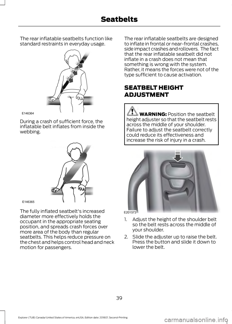
The rear inflatable seatbelts function like
standard restraints in everyday usage.
During a crash of sufficient force, the
inflatable belt inflates from inside the
webbing.
The fully inflated seatbelt's increased
diameter more effectively holds the
occupant in the appropriate seating
position, and spreads crash forces over
more area of the body than regular
seatbelts. This helps reduce pressure on
the chest and helps control head and neck
motion for passengers. The rear inflatable seatbelts are designed
to inflate in frontal or near-frontal crashes,
side impact crashes and rollovers. The fact
that the rear inflatable seatbelt did not
inflate in a crash does not mean that
something is wrong with the system.
Rather, it means the forces were not of the
type sufficient to cause activation.
SEATBELT HEIGHT
ADJUSTMENT
WARNING: Position the seatbelt
height adjuster so that the seatbelt rests
across the middle of your shoulder.
Failure to adjust the seatbelt correctly
could reduce its effectiveness and
increase the risk of injury in a crash. 1. Adjust the height of the shoulder belt
so the belt rests across the middle of
your shoulder.
2. Slide the adjuster up to raise the belt. Press the button and slide it down to
lower the belt.
39
Explorer (TUB) Canada/United States of America, enUSA, Edition date: 201807, Second-Printing SeatbeltsE146364 E146365 E201573
Page 45 of 571
4. While the seatbelt warning light is on,
buckle and then unbuckle the seatbelt.
After Step 4, the seatbelt warning light
flashes for confirmation.
• This will switch the feature off for that
seating position if it is currently on.
• This will switch the feature on for that
seating position if it is currently off.
CHILD RESTRAINT AND
SEATBELT MAINTENANCE
Inspect the vehicle seatbelts and child
restraint systems periodically to make sure
they work properly and are not damaged.
Inspect the vehicle seatbelts to make sure
there are no nicks, tears or cuts. Replace if
necessary. All vehicle seatbelt assemblies,
including retractors, buckles, front seatbelt
buckle assemblies, buckle support
assemblies (slide bar-if equipped),
shoulder belt height adjusters (if
equipped), shoulder belt guide on seatback
(if equipped), rear inflatable seatbelts (if
equipped), child restraint LATCH and
tether anchors, and attaching hardware,
should be inspected after a crash. Read
the child restraint manufacturer's
instructions for additional inspection and
maintenance information specific to the
child restraint.
We recommend that all seatbelt
assemblies in use in vehicles involved in a
crash be replaced. However, if the crash
was minor and an authorized dealer finds
that the belts do not show damage and
continue to operate properly, they do not
need to be replaced. Seatbelt assemblies
not in use during a crash should also be
inspected and replaced if either damage
or improper operation is noted.
Properly care for seatbelts. See Cleaning
the Interior (page 309). SEATBELT EXTENSION WARNING:
Persons who fit into
the vehicle's seatbelt should not use an
extension. Unnecessary use could result
in serious personal injury in the event of
a crash. WARNING:
Only use extensions
provided free of charge by Ford Motor
Company dealers. The dealer will provide
an extension designed specifically for
this vehicle, model year and seating
position. The use of an extension
intended for another vehicle, model year
or seating position may not offer you the
full protection of your vehicle ’s seatbelt
restraint system. WARNING:
Never use seatbelt
extensions to install child restraints. WARNING:
Do not use a seatbelt
extension with an inflatable seatbelt. WARNING:
Do not use extensions
to change the fit of the belt across the
torso, over the lap or to make the
seatbelt buckle easier to reach.
If, because of body size or driving position,
it is not possible to properly fasten the
seatbelt over your lap and shoulder, an
extension that is compatible with the
seatbelts is available free of charge from
Ford Motor Company dealers. Only Ford
seatbelt extensions made by the original
equipment seatbelts manufacturer should
be used with Ford seatbelts. Ask your
authorized dealer if your extension is
compatible with your Ford vehicle restraint
system.
42
Explorer (TUB) Canada/United States of America, enUSA, Edition date: 201807, Second-Printing Seatbelts
Page 75 of 571
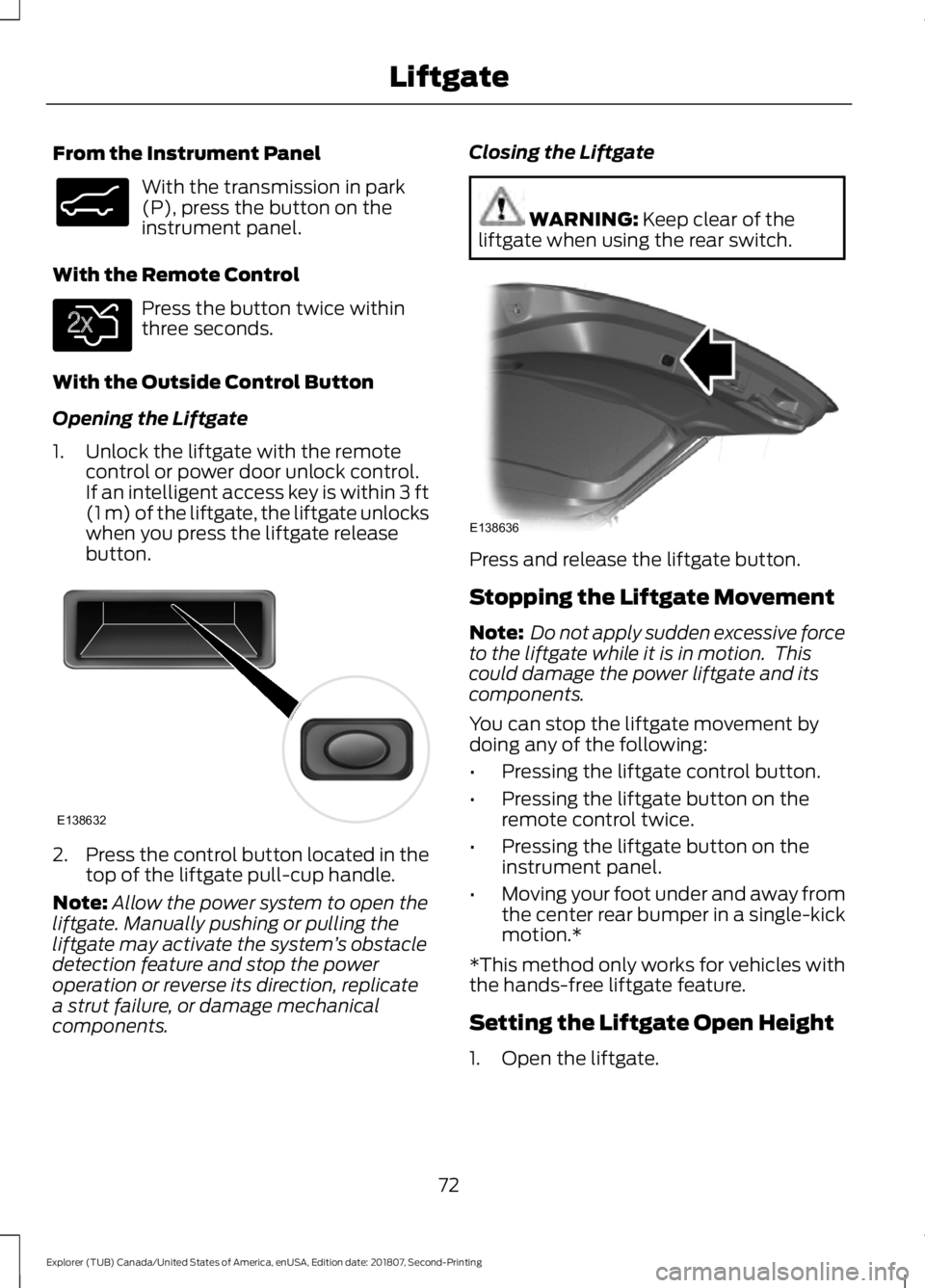
From the Instrument Panel
With the transmission in park
(P), press the button on the
instrument panel.
With the Remote Control Press the button twice within
three seconds.
With the Outside Control Button
Opening the Liftgate
1. Unlock the liftgate with the remote control or power door unlock control.
If an intelligent access key is within 3 ft
(1 m) of the liftgate, the liftgate unlocks
when you press the liftgate release
button. 2.
Press the control button located in the
top of the liftgate pull-cup handle.
Note: Allow the power system to open the
liftgate. Manually pushing or pulling the
liftgate may activate the system ’s obstacle
detection feature and stop the power
operation or reverse its direction, replicate
a strut failure, or damage mechanical
components. Closing the Liftgate WARNING:
Keep clear of the
liftgate when using the rear switch. Press and release the liftgate button.
Stopping the Liftgate Movement
Note:
Do not apply sudden excessive force
to the liftgate while it is in motion. This
could damage the power liftgate and its
components.
You can stop the liftgate movement by
doing any of the following:
• Pressing the liftgate control button.
• Pressing the liftgate button on the
remote control twice.
• Pressing the liftgate button on the
instrument panel.
• Moving your foot under and away from
the center rear bumper in a single-kick
motion.*
*This method only works for vehicles with
the hands-free liftgate feature.
Setting the Liftgate Open Height
1. Open the liftgate.
72
Explorer (TUB) Canada/United States of America, enUSA, Edition date: 201807, Second-Printing LiftgateE138633 E138630 E138632 E138636
Page 76 of 571
2.
Stop the liftgate movement by pressing
the control button on the liftgate when
it reaches the desired height.
Note: Once the liftgate has stopped
moving, you can also manually move it to
the desired height.
3. Press and hold the liftgate control button on the liftgate until you hear a
tone, indicating programming is
complete.
Note: You can only use the liftgate control
button to program the height.
Note: You cannot program the height if the
liftgate position is too low.
The new open liftgate height is recalled
when the power liftgate is opened. To
change the programmed height, repeat the
above procedure. Once you open the
power liftgate, you can manually move it
to a different height.
Note: The system recalls the new
programmed height until you reprogram it,
even if you disconnect the battery.
When operating the power liftgate after
you have programmed a lower height than
fully open, you can fully open the liftgate
by manually pushing it upward to the
maximum open position.
Obstacle Detection
When Closing
The system stops when it detects an
obstacle. A tone sounds and the system
reverses to open. Once you remove the
obstacle, you can power close the liftgate. Note:
Entering your vehicle while the
liftgate is closing can cause your vehicle to
bounce and activate obstacle detection. To
prevent this, let the power liftgate close
completely before you enter your vehicle.
Before driving off, check the instrument
cluster for a liftgate or door ajar message or
warning indicator. Failure to do this could
result in unintentionally leaving the liftgate
open while driving.
When Opening
The system stops when it detects an
obstacle and a tone sounds. Once you
remove the obstacle, you can continue to
operate the liftgate.
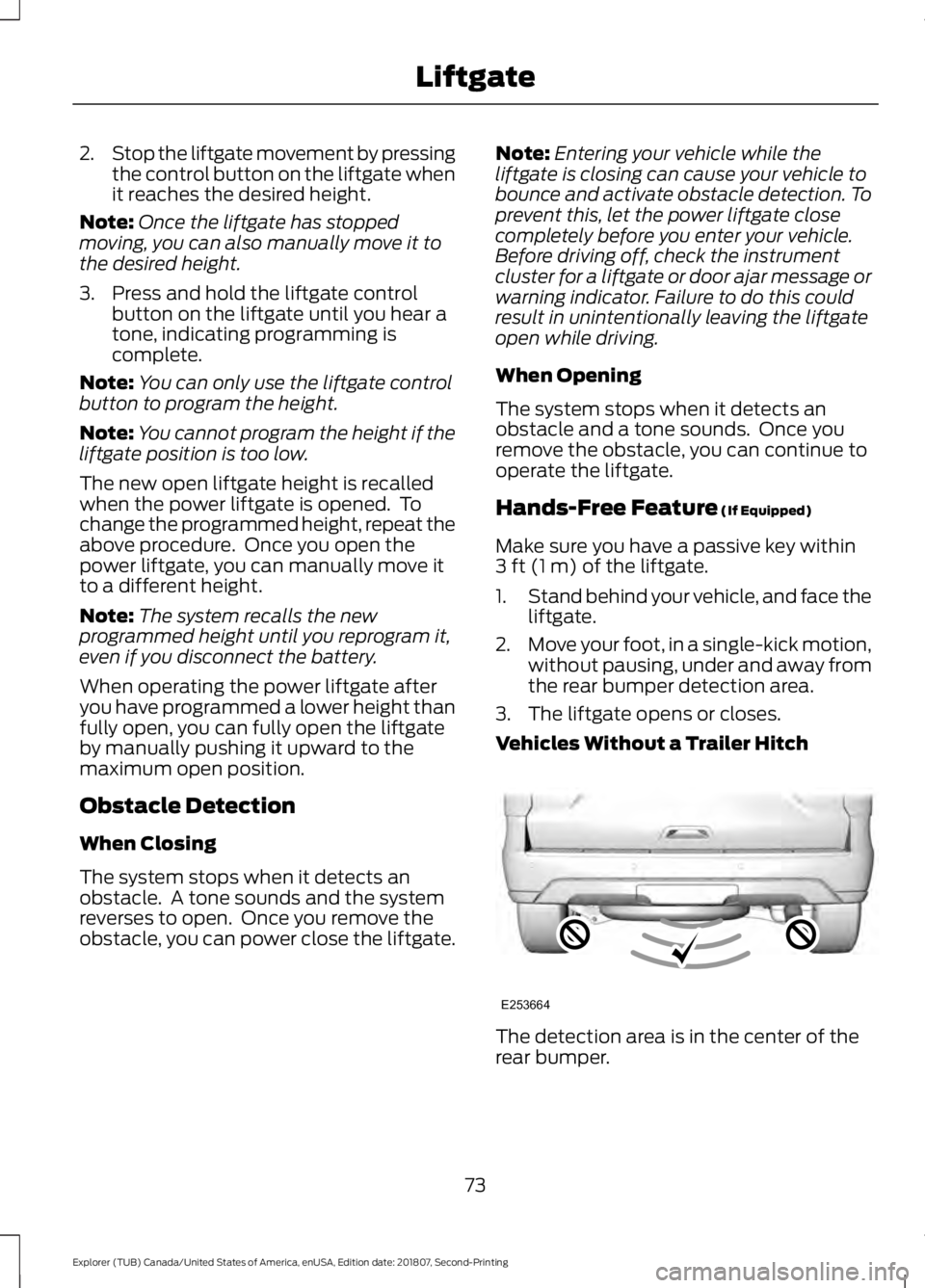
Hands-Free Feature (If Equipped)
Make sure you have a passive key within
3 ft (1 m)
of the liftgate.
1. Stand behind your vehicle, and face the
liftgate.
2. Move your foot, in a single-kick motion,
without pausing, under and away from
the rear bumper detection area.
3. The liftgate opens or closes.
Vehicles Without a Trailer Hitch The detection area is in the center of the
rear bumper.
73
Explorer (TUB) Canada/United States of America, enUSA, Edition date: 201807, Second-Printing LiftgateE253664
Page 90 of 571

The other lighting control switch positions
do not turn on the daytime running lamps.
If the daytime running lamps are off in the
information display, the lamps stay off in
all switch positions.
AUTOMATIC HIGH BEAM
CONTROL (IF EQUIPPED)
WARNING:
The system does not
relieve you of your responsibility to drive
with due care and attention. You may
need to override the system if it does not
turn the high beams on or off.
The system turns on high beams if it is dark
enough and no other traffic is present. If it
detects an approaching vehicle ’s
headlamps or tail lamps, or street lighting
ahead, the system turns off high beams
before they can distract other road users.
Low beams remain on.
Note: The system may not operate properly
if the sensor is blocked. Keep the windshield
free from obstruction or damage.
Note: The system may not operate properly
in cold or inclement conditions. You can
switch on the high beams by overriding the
system.
Note: If the system detects a blockage, for
example bird droppings, bug splatter, snow
or ice, the system goes into low beam mode
until you clear the blockage. A message may
appear in the information display if the
camera is blocked.
Note: Using much larger tires or equipping
vehicle accessories such as snowplows can
modify your vehicle's ride height and
degrade automatic high beam control
performance. A camera sensor, centrally mounted
behind the windshield of your vehicle,
continuously monitors conditions to turn
the high beams on and off.
Once the system is active, the high beams
turn on if:
•
The ambient light level is low enough.
• There is no traffic in front of your
vehicle.
• The vehicle speed is greater than
approximately 32 mph (51 km/h).
The system turns the high beams off if:
• The ambient light level is high enough
that high beams are not required.
• The system detects an approaching
vehicle's headlamps or tail lamps.
• The vehicle speed falls below
approximately
27 mph (44 km/h).
• The system detects severe rain, snow
or fog.
• The camera is blocked.
Switching the System On and Off
Switch the system on using the information
display. See Information Displays (page
104
). Switch the lighting control to the
autolamps position. See
Autolamps
(page 85).
87
Explorer (TUB) Canada/United States of America, enUSA, Edition date: 201807, Second-Printing LightingE142451
Page 253 of 571
ESSENTIAL TOWING CHECKS
Follow these guidelines for safe towing:
•
Do not tow a trailer until you drive your
vehicle at least 1,000 mi (1,600 km).
• Consult your local motor vehicle laws
for towing a trailer.
• See the instructions included with
towing accessories for the proper
installation and adjustment
specifications.
• Service your vehicle more frequently if
you tow a trailer. See your scheduled
maintenance information.
• If you use a rental trailer, follow the
instructions the rental agency gives
you.
You can find information on load
specification terms found on the tire label
and Safety Compliance label as well as
instructions on calculating your vehicle's
load in the Load Carrying chapter. See
Load Limit
(page 241).
Remember to account for the trailer
tongue weight as part of your vehicle load
when calculating the total vehicle weight.
Hitches
Do not use a hitch that either clamps onto
the bumper or attaches to the axle.
Distribute the trailer load so 10-15% of the
total trailer weight is on the tongue.
Weight-distributing Hitches WARNING:
Do not adjust the
spring bars so that your vehicle's rear
bumper is higher than before attaching
the trailer. Doing so will defeat the
function of the weight-distributing hitch,
which may cause unpredictable
handling, and could result in serious
personal injury. When hooking-up a trailer using a
weight-distributing hitch, always use the
following procedure:
1. Park the loaded vehicle, without the
trailer, on a level surface.
2. Measure the height to the top of your vehicle's front wheel opening on the
fender. This is H1.
3. Attach the loaded trailer to your vehicle
without the weight-distributing bars
connected.
4. Measure the height to the top of your vehicle's front wheel opening on the
fender a second time. This is H2.
5. Install and adjust the tension in the weight-distributing bars so that the
height of your vehicle's front wheel
opening on the fender is approximately
half the way down from H2, toward H1.
6. Check that the trailer is level or slightly
nose down toward your vehicle. If not,
adjust the ball height accordingly and
repeat Steps 2-6.
When the trailer is level or slightly nose
down toward the vehicle:
• Lock the bar tension adjuster in place.
• Check that the trailer tongue securely
attaches and locks onto the hitch.
• Install safety chains, lighting, and trailer
brake controls as required by law or the
trailer manufacturer.
Safety Chains
Note: Never attach safety chains to the
bumper.
Always connect the safety chains to the
hook retainers of your vehicle hitch.
To connect the trailer ’s safety chains, cross
them under the trailer tongue and allow
enough slack for turning tight corners. Do
not allow the chains to drag on the ground.
250
Explorer (TUB) Canada/United States of America, enUSA, Edition date: 201807, Second-Printing Towing
Page 302 of 571
Rear Window Wiper Blade
1. Lift the wiper arm.
Note:
Do not hold the wiper blade when
lifting the wiper arm.
Note: Make sure that the wiper arm does
not spring back against the glass when the
wiper blade is not attached.
2. Remove the wiper blade.
Note: Make sure that the wiper blade locks
into place.
ADJUSTING THE HEADLAMPS
Vertical Aim Adjustment
If your vehicle has been involved in a crash,
have the aim of the headlamp beam
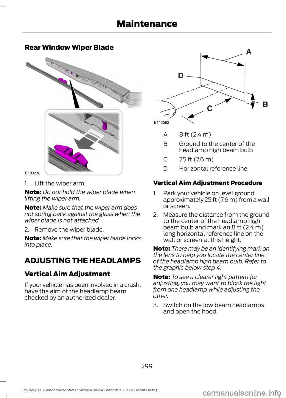
checked by an authorized dealer. 8 ft (2.4 m)
A
Ground to the center of the
headlamp high beam bulb
B
25 ft (7.6 m)
C
Horizontal reference line
D
Vertical Aim Adjustment Procedure
1. Park your vehicle on level ground approximately 25 ft (7.6 m) from a wall
or screen.
2. Measure the distance from the ground
to the center of the headlamp high
beam bulb and mark an
8 ft (2.4 m)
long horizontal reference line on the
wall or screen at this height.
Note: There may be an identifying mark on
the lens to help you locate the center line
of the headlamp high beam bulb. Refer to
the graphic below step 4.
Note: To see a clearer light pattern for
adjusting, you may want to block the light
from one headlamp while adjusting the
other.
3. Switch on the low beam headlamps and open the hood.
299
Explorer (TUB) Canada/United States of America, enUSA, Edition date: 201807, Second-Printing MaintenanceE183236 E142592
Page 322 of 571
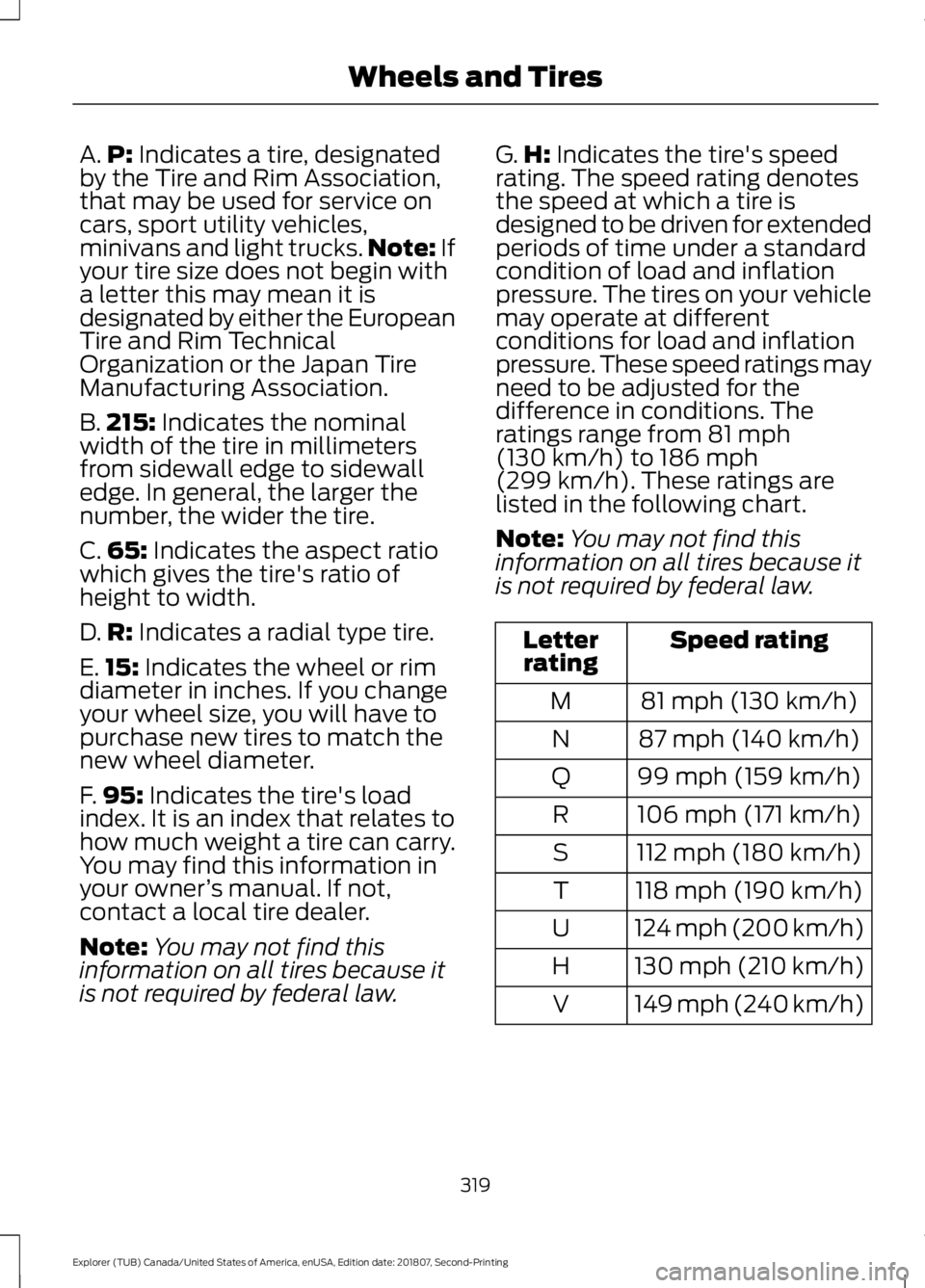
A.
P: Indicates a tire, designated
by the Tire and Rim Association,
that may be used for service on
cars, sport utility vehicles,
minivans and light trucks. Note:
If
your tire size does not begin with
a letter this may mean it is
designated by either the European
Tire and Rim Technical
Organization or the Japan Tire
Manufacturing Association.
B. 215:
Indicates the nominal
width of the tire in millimeters
from sidewall edge to sidewall
edge. In general, the larger the
number, the wider the tire.
C. 65:
Indicates the aspect ratio
which gives the tire's ratio of
height to width.
D. R:
Indicates a radial type tire.
E. 15:
Indicates the wheel or rim
diameter in inches. If you change
your wheel size, you will have to
purchase new tires to match the
new wheel diameter.
F. 95:
Indicates the tire's load
index. It is an index that relates to
how much weight a tire can carry.
You may find this information in
your owner ’s manual. If not,
contact a local tire dealer.
Note: You may not find this
information on all tires because it
is not required by federal law. G.
H:
Indicates the tire's speed
rating. The speed rating denotes
the speed at which a tire is
designed to be driven for extended
periods of time under a standard
condition of load and inflation
pressure. The tires on your vehicle
may operate at different
conditions for load and inflation
pressure. These speed ratings may
need to be adjusted for the
difference in conditions. The
ratings range from
81 mph
(130 km/h) to 186 mph
(299 km/h). These ratings are
listed in the following chart.
Note: You may not find this
information on all tires because it
is not required by federal law. Speed rating
Letter
rating
81 mph (130 km/h)
M
87 mph (140 km/h)
N
99 mph (159 km/h)
Q
106 mph (171 km/h)
R
112 mph (180 km/h)
S
118 mph (190 km/h)
T
124 mph (200 km/h)
U
130 mph (210 km/h)
H
149 mph (240 km/h)
V
319
Explorer (TUB) Canada/United States of America, enUSA, Edition date: 201807, Second-Printing Wheels and Tires