2019 FORD E-450 instrument cluster
[x] Cancel search: instrument clusterPage 60 of 329

Tow Haul Indicator
Illuminates when the driver
activates the tow/haul feature.
If the light flashes steadily, have
an authorized dealer check the system
immediately, damage to the transmission
could occur.
AUDIBLE WARNINGS AND
INDICATORS
Fail-Safe Cooling Warning Chime
Sounds when the coolant gauge pointer
has moved to hot. There are three stages
of chimes:
• Stage 1 is a single chime when the
engine temperature begins to overheat.
• Stage 2 is multiple chimes and engine
power becomes limited in order to help
cool the engine.
• Stage 3 is multiple chimes and the
engine will shut down.
Headlamps On Warning Chime
Sounds when you remove the key from the
ignition and open the driver's door and you
have left the headlamps or parking lamps
on.
Key in Ignition Warning Chime
Sounds when you open the driver's door
and you have left the key in the ignition.
Parking Brake On Warning Chime
Sounds when you have left the parking
brake on and drive your vehicle. If the
warning chime remains on after you have
released the parking brake, have the
system checked by your authorized dealer
immediately. Shift to Park Warning Chime
Sounds when the ignition is in the off or
accessory position and your vehicle is not
in park, or when you open the driver's door
and your vehicle is not in park.
57
E-Series (TE4) Canada/United States of America, enUSA, Edition date: 201804, Second-Printing Instrument ClusterE161509
Page 84 of 329

•
Keep the fuel pump nozzle in contact
with the fuel container while filling.
• Do not use a device that would hold
the fuel pump handle in the fill position.
Fuel Filler Cap WARNING: The fuel system may
be under pressure. If you hear a hissing
sound near the fuel filler door, do not
refuel until the sound stops. Otherwise,
fuel may spray out, which could cause
serious personal injury. WARNING:
If you do not use the
proper fuel filler cap, excessive pressure
or vacuum in the fuel tank may damage
the fuel system or cause the fuel cap to
disengage in a collision, which may result
in possible personal injury.
Note: If you must replace the fuel filler cap,
replace it with a fuel filler cap that is
designed for your vehicle. The customer
warranty may be void for any damage to the
fuel tank or fuel system if the correct
genuine Ford, Motorcraft or other certified
fuel filler cap is not used.
Your fuel tank filler cap has an indexed
design with a 1/4th turn on and off feature.
When fueling your vehicle:
1. Put your vehicle in park (P).
2. Switch the engine off.
3. Carefully turn the filler cap counterclockwise until it spins off.
4. Pull to remove the cap from the fuel filler pipe.
5. To install the cap, align the tabs on the
cap with the notches on the filler pipe.
6. Turn the filler cap clockwise 1/4 of a turn clockwise until it clicks at least
once. If the Check Fuel Cap light or a Check Fuel
Cap message appears in the instrument
cluster and stays on after you start the
engine, you may not have installed the fuel
filler properly.
If the fuel cap light remains on, at the next
opportunity, safely pull off of the road,
remove the fuel filler cap, align the cap
properly and reinstall it. The check fuel cap
light or Check fuel cap message may not
reset immediately. It may take several
driving cycles for the indicators to turn off.
A driving cycle consists of an engine
start-up (after four or more hours with the
engine off) followed by normal city and
highway driving.
FUEL CONSUMPTION
Advertised Capacity
The advertised capacity is the maximum
amount of fuel that you can add to the fuel
tank after running out of fuel. Included in
the advertised capacity is an empty
reserve. The empty reserve is an
unspecified amount of fuel that remains
in the fuel tank when the fuel gauge
indicates empty.
Note:
The amount of fuel in the empty
reserve varies and should not be relied upon
to increase driving range.
Fuel Economy
Your vehicle calculates fuel economy
figures through the trip computer average
fuel function. See
General Information
(page 58).
The first
1,000 mi (1,500 km) of driving is
the break-in period of the engine. A more
accurate measurement is obtained after
2,000 mi (3,000 km)
.
81
E-Series (TE4) Canada/United States of America, enUSA, Edition date: 201804, Second-Printing Fuel and Refueling
Page 91 of 329

Tow/Haul Mode
To activate tow/haul, press the
button on the gearshift lever.
The TOW HAUL indicator light
illuminates in the instrument cluster.
The tow/haul feature:
• Delays upshifts to reduce the frequency
of transmission shifting.
• Provides engine braking in all forward
gears, which slows your vehicle and
assists you in controlling your vehicle
when descending a slope.
• Depending on driving conditions and
load conditions, may downshift the
transmission, slow your vehicle and
control your vehicle speed when
descending a hill, without pressing the
accelerator pedal. The amount of
downshift braking provided will vary
based upon the amount you press the
brake pedal.
The tow/haul feature improves
transmission operation when towing a
trailer or a heavy load. All transmission
gear ranges are available when using
tow/haul.
To deactivate the tow/haul feature and
return to normal driving mode, press the
button on the gearshift lever again. The
TOW HAUL light deactivates. Tow/haul
also deactivates when you power down
your vehicle. WARNING: Do not use tow/haul
when the road surface is slippery. Failure
to follow this instruction could result in
the loss of control of your vehicle. Brake-Shift Interlock WARNING:
When doing this
procedure, you need to take the
transmission out of park (P) which
means your vehicle can roll freely. To
avoid unwanted vehicle movement,
always fully apply the parking brake prior
to doing this procedure. Use wheels
chocks if appropriate. WARNING:
If the parking brake is
fully released, but the brake warning
lamp remains illuminated, the brakes
may not be working properly. Have your
vehicle checked as soon as possible.
Note: Do not drive your vehicle until you
verify that the brake lamps are working.
Your vehicle has a brake-shift interlock
feature that prevents the gearshift lever
from moving from park (P) when the
ignition is in the 3 (on) position and the
brake pedal is not pressed.
If you cannot move the gearshift lever out
of park (P) position with the ignition in the
4 (on) position and the brake pedal
pressed, a malfunction may have occurred.
It is possible that a fuse has blown or your
vehicle ’s brake lamps are not operating
properly.
See Fuse Specification Chart
(page 131).
If the fuse is not blown and the brake
lamps are working properly, the following
procedure allows you to move the gearshift
lever from park (P):
1. Apply the parking brake and turn the ignition on.
2. Use a screwdriver to remove the lower
trim panel under the steering column.
Make sure not to disturb the wires on
the electrical connector.
88
E-Series (TE4) Canada/United States of America, enUSA, Edition date: 201804, Second-Printing TransmissionE161509
Page 96 of 329

PRINCIPLE OF OPERATION
The traction control system helps avoid
drive wheel spin and loss of traction.
If your vehicle begins to slide, the system
applies the brakes to individual wheels
and, when needed, reduces engine power
at the same time. If the wheels spin when
accelerating on slippery or loose surfaces,
the system reduces engine power in order
to increase traction.
USING TRACTION CONTROL
WARNING: The traction control
light illuminates steadily if a failure is
detected in the system. Verify that the
traction control system was not
manually disabled using the switch. If
the traction control light is still
illuminating steadily, have the system
serviced by an authorized dealer
immediately. Operating your vehicle with
traction control disabled could lead to
an increased risk of loss of vehicle
control, vehicle rollover, personal injury
and death.
The system automatically turns on each
time you switch the ignition on.
If your vehicle is stuck in mud or snow,
switching traction control off may be
beneficial as this allows the wheels to spin.
Switching the System Off The switch for the traction
control system is located on the
instrument panel.
When you switch the system off, an
illuminated icon appears on the instrument
cluster.
Use the switch again to return the traction
control system to normal operation. System Indicator Lights and
Messages The traction control light
temporarily illuminates on
engine start-up and flashes
when a driving condition activates the
system. The traction control off light
temporarily illuminates on
engine start-up and stays on:
• When you switch the traction control
system off.
• If a problem occurs in the system.
93
E-Series (TE4) Canada/United States of America, enUSA, Edition date: 201804, Second-Printing Traction Control
(If Equipped)E194301 E138639 E194301
Page 99 of 329

PRINCIPLE OF OPERATION
Cruise control lets you maintain a set
speed without keeping your foot on the
accelerator pedal. You can use cruise
control when your vehicle speed is greater
than 20 mph (30 km/h).
USING CRUISE CONTROL WARNING:
Do not use cruise
control on winding roads, in heavy traffic
or when the road surface is slippery. This
could result in loss of vehicle control,
serious injury or death. WARNING:
When you are going
downhill, your vehicle speed could
increase above the set speed. The
system does not apply the brakes.
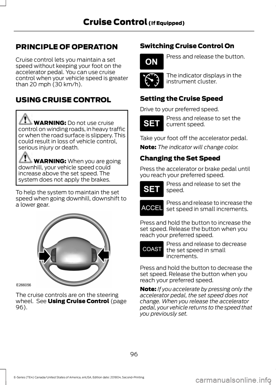
To help the system to maintain the set
speed when going downhill, downshift to
a lower gear. The cruise controls are on the steering
wheel. See
Using Cruise Control (page
96). Switching Cruise Control On Press and release the button.
The indicator displays in the
instrument cluster.
Setting the Cruise Speed
Drive to your preferred speed. Press and release to set the
current speed.
Take your foot off the accelerator pedal.
Note: The indicator will change color.
Changing the Set Speed
Press the accelerator or brake pedal until
you reach your preferred speed. Press and release to set the
speed.
Press and release to increase the
set speed in small increments.
Press and hold the button to increase the
set speed. Release the button when you
reach your preferred speed. Press and release to decrease
the set speed in small
increments.
Press and hold the button to decrease the
set speed. Release the button when you
reach your preferred speed.
Note: If you accelerate by pressing only the
accelerator pedal, the set speed does not
change. When you release the accelerator
pedal, your vehicle returns to the speed that
you previously set.
96
E-Series (TE4) Canada/United States of America, enUSA, Edition date: 201804, Second-Printing Cruise Control
(If Equipped)E266056 E265296 E71340 E265306 E265306 E266055 E266054
Page 138 of 329

Protected Component
Fuse Rating
Fuse or Relay
Number
Power point 1 (instrument panel).
20A 2
67
Modified vehicle.
50A 2
68
Not used.
—
69
Stripped chassis.
30A 2
70
Not used.
—
71
Cigarette lighter/power point.
20A 2
72
Not used.
—
73
Power seat.
30A 2
74
Vehicle power 1.
20A 3
75
Powertrain control module power.
Vehicle power 2.
20A 3
76
Powertrain control module emissions
related components.
Vehicle power 3.
10A 3
77
Powertrain control module general
components.
Vehicle power 4.
15A 3
78
Engine ignition coil relay coil.
Vehicle power 5.
10A 3
79
Transmission.
Cluster run/start (stripped chassis).
10A 3
80
Not used.
—
81
Not used.
—
82
Fuel pump diode.
—
83
135
E-Series (TE4) Canada/United States of America, enUSA, Edition date: 201804, Second-Printing Fuses
Page 141 of 329

Protected Component
Fuse Rating
Fuse or Relay
Number
Ignition switch feed.
20A
27
Audio mute (start).
5A
28
Cluster (except stripped chassis).
5A
29
Not used (spare).
5A
30
Not used (spare).
10A
31
Restraints module.
10A
32
Trailer brake controller.
10A
33
Not used (spare).
5A
34
Cutaway run/start.
10A
35
Passive anti-theft system radio frequency
module.
5A
36
Climate control.
10A
37
Stripped chassis #1 run/start.
Not used (spare).
20A
38
Radio.
20A
39
Not used (spare).
20A
40
Radio.
15A
41
Switch illumination.
Automatic dimming rear view mirror.
Power inverter.
Auxiliary switch.
10A
42
Stripped chassis instrument panel
connector #1.
10A
43
Trailer tow battery charge relay.
10A
44
Wipers.
5A
45
Stripped chassis engine connector 3.
Passenger airbag deactivation indicator.
7.5A
46
Windows accessory delay circuit breaker.
30A
47
Delayed accessory relay.
—
48
138
E-Series (TE4) Canada/United States of America, enUSA, Edition date: 201804, Second-Printing Fuses
Page 152 of 329

1. Pull off the road as soon as safely
possible and shift the transmission into
park (P).
2. Leave the engine running until the coolant temperature gauge needle
returns to the normal position. If the
temperature does not drop after
several minutes, follow the remaining
steps.
3. Switch the engine off and wait for it to
cool. Check the coolant level.
4. If the coolant level is at or below the minimum mark, immediately add
prediluted coolant.
5. If the coolant level is normal, restart the engine and continue driving.
AUTOMATIC TRANSMISSION
FLUID CHECK
Have an authorized dealer check and
change the transmission fluid and filter at
the correct service interval. See
Scheduled Maintenance (page 276).
Do not use supplemental transmission
fluid additives, treatments or cleaning
agents. The use of these materials may
affect transmission operation and result
in damage to internal transmission
components.
Checking Automatic Transmission
Fluid
For scheduled intervals of the fluid checks
and changes, See
Scheduled
Maintenance (page 276). Your
transmission does not consume fluid.
However, the fluid level should be checked
if the transmission is not working properly,
i.e., if the transmission slips or shifts slowly
or if you notice some sign of fluid leakage. Automatic transmission fluid expands
when warmed. To obtain an accurate fluid
check, drive the vehicle until it is at normal
operating temperature (approximately
19 mi (30 km)
). Verify that the
transmission fluid temperature gauge,
located on the instrument cluster, is within
normal range.
1. Drive the vehicle
19 mi (30 km) until it
reaches normal operating temperature.
2. Park the vehicle on a level surface and
engage the parking brake.
3. With the engine running, parking brake
engaged and your foot on the brake
pedal, move the gearshift lever through
all of the gear ranges. Allow sufficient
time for each gear to engage.
4. Put the transmission in park (P) and leave the engine running.
5. Remove the dipstick, wiping it clean with a clean, dry lint free rag. If
necessary, refer to the Under Hood
Overview in this chapter for the
location of the dipstick.
6. Install the dipstick making sure it is fully
seated in the filler tube.
7. Remove the dipstick and inspect the fluid level. The fluid should be in the
designated area for normal operating
temperature or ambient temperature.
Low Fluid Level
Type A
149
E-Series (TE4) Canada/United States of America, enUSA, Edition date: 201804, Second-Printing Maintenance