2019 FORD E-350 lock
[x] Cancel search: lockPage 161 of 329

4. Remove the bulb assembly by turning
it counterclockwise and pulling it
straight out.
To install the new bulb, follow the removal
procedures in reverse order.
Replacing Front Parking Lamp and
Direction Indicator Bulbs 1. Make sure the headlamp switch is in
the off position, then open the hood.
2. Remove the headlamp assembly. Refer
to Replacing Headlamp Bulbs in this
section.
3. Rotate the bulb socket counterclockwise and remove.
4. Carefully pry up the bulb straight out of the socket.
To complete installation, follow the
removal procedures in reverse order. Replacing Side Marker Bulbs
1. Make sure the headlamp switch is in
the off position, then open the hood.
2. Remove the headlamp assembly. Refer
to
Replacing Headlamp Bulbs in this
section.
3. Rotate the bulb socket counterclockwise and remove.
4. Carefully pry up the bulb straight out of the socket.
To complete installation, follow the
removal procedures in reverse order.
Replacing
Brake/Tail/Turn/Reverse Lamp
Bulbs (Cut-Away Only)
1. Make sure the headlamps are off. 158
E-Series (TE4) Canada/United States of America, enUSA, Edition date: 201804, Second-Printing MaintenanceE196386 E196388 E196390 E163828
Page 165 of 329
WAXING
Regular waxing is necessary to protect your
car's paint from the elements. We
recommend that you wash and wax the
painted surface once or twice a year.
When washing and waxing, park your
vehicle in a shaded area out of direct
sunlight. Always wash your vehicle before
applying wax.
•
Use a quality wax that does not contain
abrasives.
• Follow the manufacturer ’s instructions
to apply and remove the wax.
• Apply a small amount of wax in a
back-and-forth motion, not in circles.
• Do not allow wax to come in contact
with any non-body (low-gloss black)
colored trim. The wax will discolor or
stain the parts over time.
•Roof racks.
• Bumpers.
• Grained door handles.
• Side moldings.
• Mirror housings.
• Windshield cowl area.
• Do not apply wax to glass areas.
• After waxing, your car's paint should
feel smooth, and be free of streaks and
smudges.
CLEANING THE ENGINE
Engines are more efficient when they are
clean because grease and dirt buildup keep
the engine warmer than normal. When washing:
•
Take care when using a power washer
to clean the engine. The high-pressure
fluid could penetrate the sealed parts
and cause damage.
• Do not spray a hot engine with cold
water to avoid cracking the engine
block or other engine components.
• Spray Motorcraft Engine Shampoo and
Degreaser on all parts that require
cleaning and pressure rinse clean. In
Canada, use Motorcraft Engine
Shampoo.
Note: If your vehicle has an engine cover
remove the cover before application of
Motorcraft Engine Shampoo and Degreaser.
Immediately rinse away any over spray.
• Never wash or rinse the engine while it
is hot or running; water in the running
engine may cause internal damage.
• Never wash or rinse any ignition coil,
spark plug wire or spark plug well, or
the area in and around these locations.
• Cover the battery, power distribution
box, and air filter assembly to prevent
water damage when cleaning the
engine.
CLEANING THE WINDOWS AND
WIPER BLADES
Car wash chemicals and environmental
fallout can result in windshield and wiper
blade contamination. Dirty windshield and
wipers will result in poor windshield wiper
operation. Keep the windshield and wiper
blades clean to maintain windshield wiper
performance.
162
E-Series (TE4) Canada/United States of America, enUSA, Edition date: 201804, Second-Printing Vehicle Care
Page 195 of 329

3. Cycle the ignition to the on position
with the engine off.
4. Turn the hazard flashers on then off three times. You must accomplish this
within 10 seconds. If you successfully
enter the reset mode, the horn sounds
once, the system indicator flashes and
a message shows in the information
display. If this does not occur, please
try again starting at step 2. If after
repeated attempts to enter the reset
mode, the horn does not sound, the
system indicator does not flash and no
message shows in the information
display, have the system checked as
soon as possible.
5. Train the tire pressure monitoring system sensors in the tires using the
following system reset sequence
starting with the left front tire in the
following clockwise order: Left front -
driver side front tire, Right front -
passenger side front tire, Right rear -
passenger side rear tire, Left rear -
driver side rear tire.
6. Remove the valve cap from the valve stem on the left front tire. Decrease the
air pressure until the horn sounds.
Note: The single horn tone confirms that
the sensor identification code has been
learned by the module for this position. If
you hear a double horn, the reset procedure
was unsuccessful, and you must repeat it.
7. Remove the valve cap from the valve stem on the right front tire. Decrease
the air pressure until the horn sounds.
8. Remove the valve cap from the valve stem on the right rear tire. Decrease the
air pressure until the horn sounds. 9. Remove the valve cap from the valve
stem on the left rear tire. Decrease the
air pressure until the horn sounds.
Training is complete after the horn
sounds for the last tire trained, driver
side rear tire, the system indicator
stops flashing, and a message shows
in the information display.
10. Turn the ignition off. If you hear two short tones, the reset procedure was
unsuccessful and you must repeat it.
If you hear two short beeps when the
ignition is off after repeating the
procedure, have the system checked
as soon as possible
11. Set all four tires to the recommended
air pressure as indicated on the
Safety Compliance Certification
Label, affixed to either the door hinge
pillar, door-latch post, or the door
edge that meets the door-latch post,
next to the driver seating position or
Tire Label located on the B-Pillar or
the edge of the driver door.
CHANGING A ROAD WHEEL WARNING: To determine the
required pressure(s) for your vehicle, see
the Safety Compliance Certification
Label (on the door hinge pillar,
door-latch post or the door edge that
meets the door-latch post, next to the
driver seat) or the Tire Label on the
B-Pillar or the edge of the driver door.
Note: You should only use tire sealants in
roadside emergencies as they may cause
damage to the tire pressure monitoring
system sensor.
192
E-Series (TE4) Canada/United States of America, enUSA, Edition date: 201804, Second-Printing Wheels and Tires
Page 197 of 329
When driving with the full-size dissimilar
spare wheel and tire assembly, do not:
•
Exceed 70 mph (113 km/h).
• Use more than one dissimilar spare
wheel and tire assembly at a time.
• Use commercial car washing
equipment.
• Use snow chains on the end of the
vehicle with the dissimilar spare wheel
and tire assembly.
The usage of a full-size dissimilar spare
wheel and tire assembly can lead to
impairment of the following:
• Handling, stability and braking
performance.
• Comfort and noise.
• Ground clearance and parking at curbs.
• Winter weather driving capability.
• Wet weather driving capability.
• All-wheel driving capability.
When driving with the full-size dissimilar
spare wheel and tire assembly additional
caution should be given to:
• Towing a trailer.
• Driving vehicles equipped with a
camper body.
• Driving vehicles with a load on the
cargo rack.
Drive cautiously when using a full-size
dissimilar spare wheel and tire assembly
and seek service as soon as possible.
Tire Change Procedure WARNING:
When one of the front
wheels is off the ground, the
transmission alone will not prevent the
vehicle from moving or slipping off the
jack, even if the transmission is in park
(P). WARNING:
To help prevent your
vehicle from moving when changing a
wheel, shift the transmission into park
(P), set the parking brake and use an
appropriate block or wheel chock to
secure the wheel diagonally opposite to
the wheel being changed. For example,
when changing the front left wheel,
place an appropriate block or wheel
chock on the right rear wheel. WARNING:
Do not get under a
vehicle that is only supported by a
vehicle jack. WARNING:
Do not attempt to
change a tire on the side of the vehicle
close to moving traffic. Pull far enough
off the road to avoid the danger of being
hit when operating the jack or changing
the wheel. WARNING:
Always use the jack
provided as original equipment with your
vehicle. If using a jack other than the one
provided, make sure the jack capacity is
adequate for the vehicle weight,
including any vehicle cargo or
modifications. If you are unsure if the jack
capacity is adequate, contact the
authorized dealer.
Note: Passengers should not remain in your
vehicle when the vehicle is being jacked.
Removing the flat wheel and tire
1. Park on a level surface, set the parking
brake and activate the hazard flashers.
2. Place the transmission in park (P) and
turn the engine off.
194
E-Series (TE4) Canada/United States of America, enUSA, Edition date: 201804, Second-Printing Wheels and Tires
Page 198 of 329

3.
Block both directions of the wheel that
is diagonally opposite to the wheel that
is being lifted.
4. Remove the spare tire and jack from the storage location.
5. Remove the wheel trim (if equipped) by inserting the tapered end of the lug
nut wrench behind the wheel cover or
hubcap and twist it off.
6. Loosen each wheel lug nut one-half turn counterclockwise, but do not
remove them until the wheel is raise
off the ground.
Jacking location Front axle jacking point: Place the jack
under the pin on the front surface of the
front axle. Note:
Do not place the jack under or on the
steering linkage. Rear axle jacking points: All models except
E-350 and E-450 dual rear wheel.
Rear axle jacking points: E-350 and E-450
dual rear wheel.
Installing the spare wheel and tire
1. Refer to the diagrams above to locate
the correct jacking point for your
vehicle.
2. Raise the vehicle by using the jack handle to turn the jack nut clockwise.
Once the flat tire is raised above the
ground, remove the lug nuts with the
lug wrench.
3. Replace the flat tire with the spare tire,
making sure the valve stem is facing
outward. Reinstall the lug nuts until the
wheel is snug against the hub. Do not
fully tighten the lug nuts until the wheel
has been lowered.
195
E-Series (TE4) Canada/United States of America, enUSA, Edition date: 201804, Second-Printing Wheels and TiresE142551 E201348 E201346 E201347
Page 199 of 329
4. Lower the wheel by turning the jack
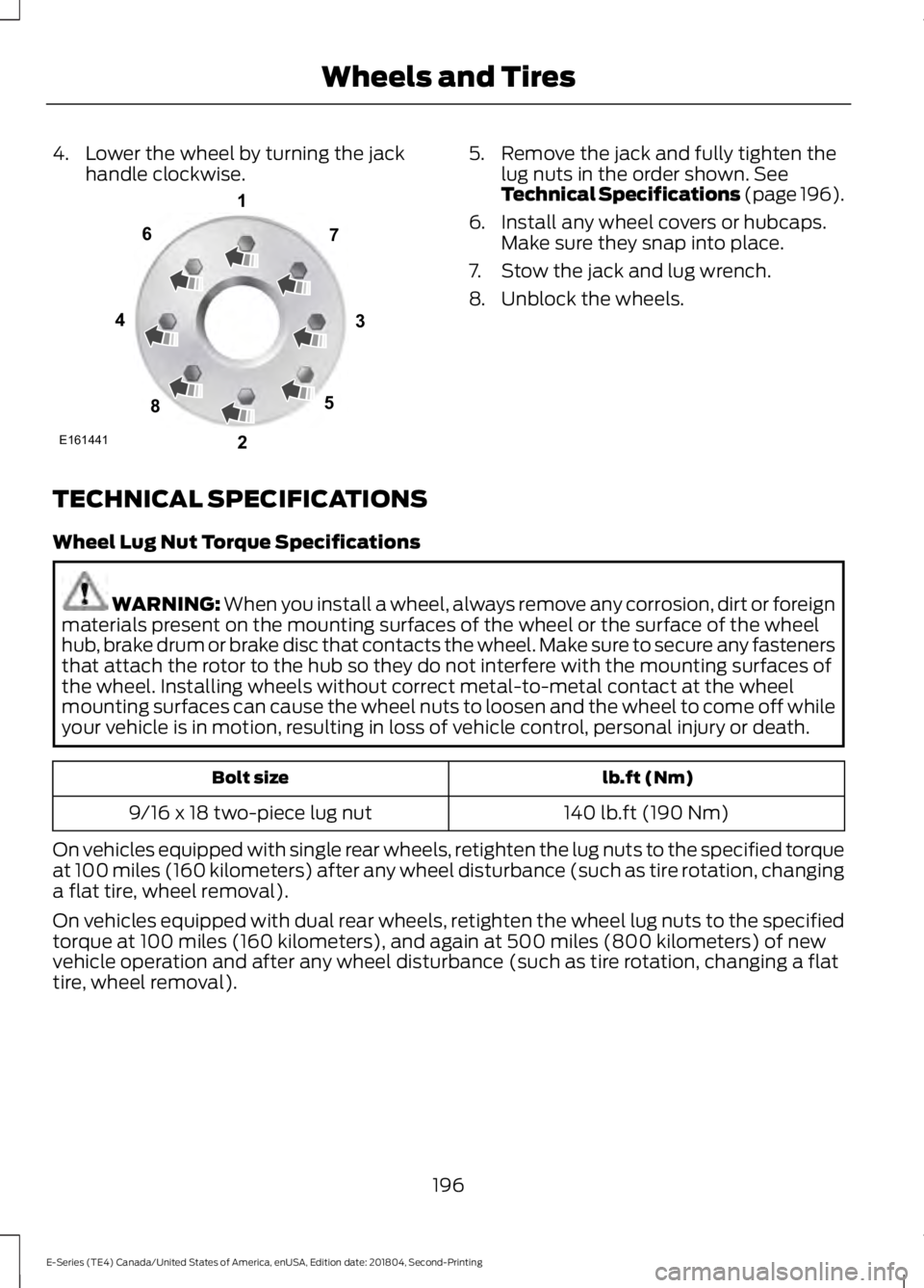
handle clockwise. 5. Remove the jack and fully tighten the
lug nuts in the order shown. See
Technical Specifications (page 196).
6. Install any wheel covers or hubcaps. Make sure they snap into place.
7. Stow the jack and lug wrench.
8. Unblock the wheels.
TECHNICAL SPECIFICATIONS
Wheel Lug Nut Torque Specifications WARNING:
When you install a wheel, always remove any corrosion, dirt or foreign
materials present on the mounting surfaces of the wheel or the surface of the wheel
hub, brake drum or brake disc that contacts the wheel. Make sure to secure any fasteners
that attach the rotor to the hub so they do not interfere with the mounting surfaces of
the wheel. Installing wheels without correct metal-to-metal contact at the wheel
mounting surfaces can cause the wheel nuts to loosen and the wheel to come off while
your vehicle is in motion, resulting in loss of vehicle control, personal injury or death. lb.ft (Nm)
Bolt size
140 lb.ft (190 Nm)
9/16 x 18 two-piece lug nut
On vehicles equipped with single rear wheels, retighten the lug nuts to the specified torque
at 100 miles (160 kilometers) after any wheel disturbance (such as tire rotation, changing
a flat tire, wheel removal).
On vehicles equipped with dual rear wheels, retighten the wheel lug nuts to the specified
torque at 100 miles (160 kilometers), and again at 500 miles (800 kilometers) of new
vehicle operation and after any wheel disturbance (such as tire rotation, changing a flat
tire, wheel removal).
196
E-Series (TE4) Canada/United States of America, enUSA, Edition date: 201804, Second-Printing Wheels and TiresE161441
13
4
27
6
5
8
Page 209 of 329
Specification
Name
YN-12-D ESB-M1C93-B
Multi-purpose grease:
Motorcraft® Multi-Purpose Grease Spray
XL-5-A
-
Lock cylinders (U.S.):
Penetrating and Lock Lubricant
XL-1
-
Lock cylinders (Canada):
Penetrating Fluid
CXC-51-A
-
Lock cylinders (Mexico):
Penetrating and Lock Lubricant
MXL-1
ESR-M13P4-A
Door weatherstrips:
Silicone Spray Lubricant
XL-6
Note: The engine antifreeze/coolant color
approved to our Specification
WSS-M97B57-A2 is yellow.
If you use oil and fluids that do not meet
the defined specification and viscosity
grade, this may lead to:
• Component damage that your vehicle
warranty does not cover.
• Longer engine cranking periods.
• Increased emission levels.
• Reduced engine performance.
• Reduced fuel economy.
• Reduced brake performance.
We recommend Motorcraft® motor oil for
your vehicle. If Motorcraft® oil is not
available, use motor oils of the
recommended viscosity grade that meet
API SN Plus requirements and display the
API Certification Mark for gasoline engines.
Do not use oil labeled with API SN service
category unless the label also displays the
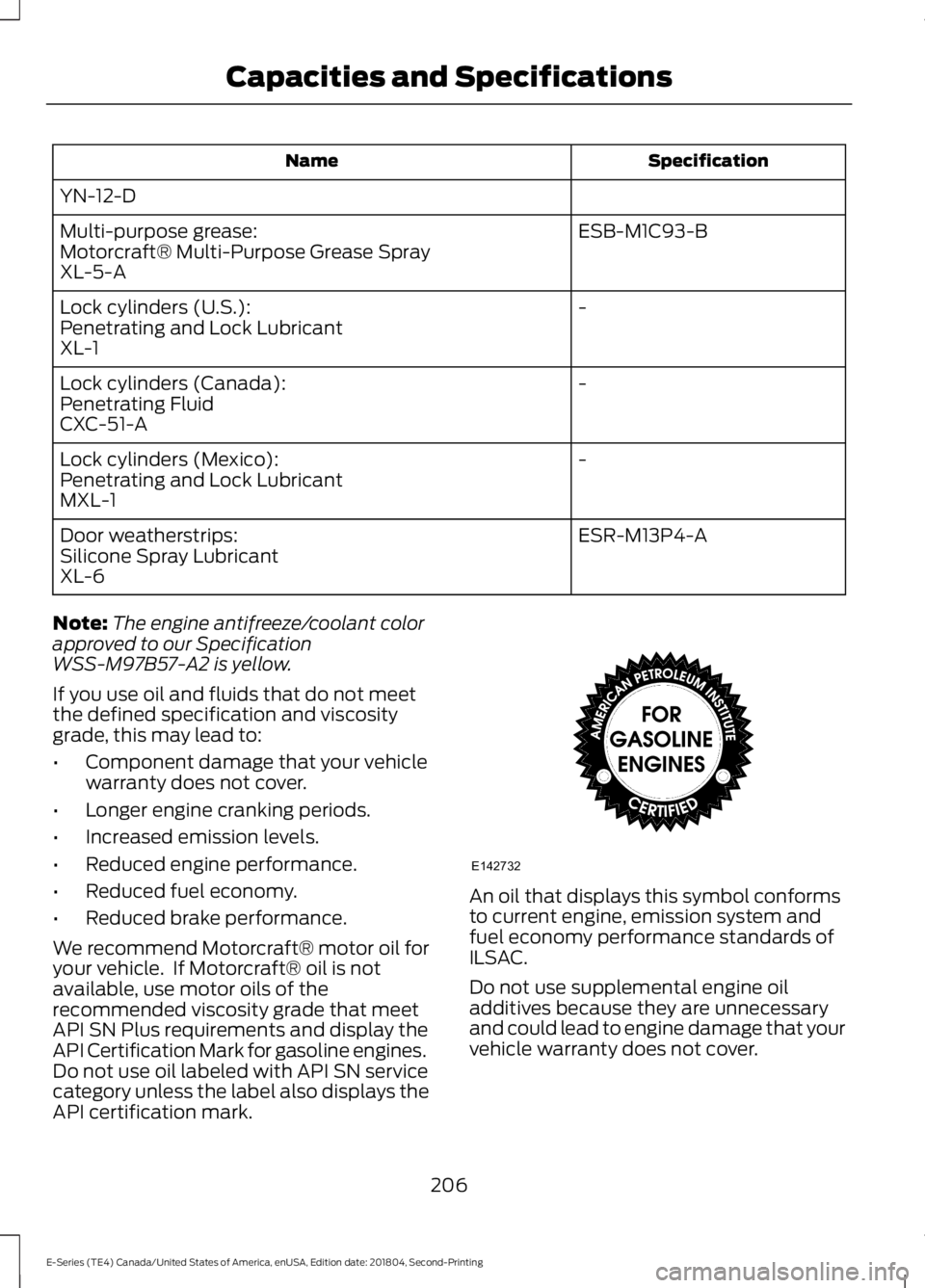
API certification mark. An oil that displays this symbol conforms
to current engine, emission system and
fuel economy performance standards of
ILSAC.
Do not use supplemental engine oil
additives because they are unnecessary
and could lead to engine damage that your
vehicle warranty does not cover.
206
E-Series (TE4) Canada/United States of America, enUSA, Edition date: 201804, Second-Printing Capacities and SpecificationsE142732
Page 213 of 329
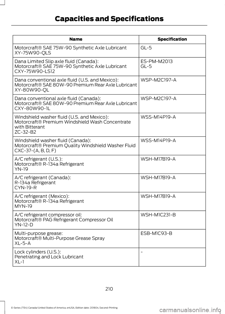
Specification
Name
GL-5
Motorcraft® SAE 75W-90 Synthetic Axle Lubricant
XY-75W90-QLS
ES-PM-M2013
Dana Limited Slip axle fluid (Canada):
GL-5
Motorcraft® SAE 75W-90 Synthetic Axle Lubricant
CXY-75W90-LS12
WSP-M2C197-A
Dana conventional axle fluid (U.S. and Mexico):
Motorcraft® SAE 80W-90 Premium Rear Axle Lubricant
XY-80W90-QL
WSP-M2C197-A
Dana conventional axle fluid (Canada):
Motorcraft® SAE 80W-90 Premium Rear Axle Lubricant
CXY-80W90-1L
WSS-M14P19-A
Windshield washer fluid (U.S. and Mexico):
Motorcraft® Premium Windshield Wash Concentrate
with Bitterant
ZC-32-B2
WSS-M14P19-A
Windshield washer fluid (Canada):
Motorcraft® Premium Quality Windshield Washer Fluid
CXC-37-(A, B, D, F)
WSH-M17B19-A
A/C refrigerant (U.S.):
Motorcraft® R-134a Refrigerant
YN-19
WSH-M17B19-A
A/C refrigerant (Canada):
R-134a Refrigerant
CYN-19-R
WSH-M17B19-A
A/C refrigerant (Mexico):
Motorcraft® R-134a Refrigerant
MYN-19
WSH-M1C231-B
A/C refrigerant compressor oil:
Motorcraft® PAG Refrigerant Compressor Oil
YN-12-D
ESB-M1C93-B
Multi-purpose grease:
Motorcraft® Multi-Purpose Grease Spray
XL-5-A
-
Lock cylinders (U.S.):
Penetrating and Lock Lubricant
XL-1
210
E-Series (TE4) Canada/United States of America, enUSA, Edition date: 201804, Second-Printing Capacities and Specifications