Page 48 of 332

Manual Climate Control Descriptions
IconDescription
A/C Button
Push the A/C button to engage the Air Conditioning (A/C). A LED will illuminate when the
A/C system is engaged.
Recirculation Setting
Rotate this control to change the system between recirculation mode and outside air mode. Re-
circulation can be used when outside air conditions such as smoke, odors, dust, or high humid-
ity are present. Recirculation can be used in all modes except for Defrost. Recirculation may be
unavailable if conditions exist that could create fogging on the inside of the windshield. The
A/C can be deselected manually without disturbing the mode control selection. Continuous use
of the Recirculation mode may make the inside air stuffy and window fogging may occur.
Extended use of this mode is not recommended.
Temperature Control
Use this control to regulate the temperature of the air inside the interior cabin. Rotating the
knob counterclockwise, from top center into the blue area of the scale, indicates cooler tempera-
tures. Rotating the knob clockwise, into the red area, indicates warmer temperatures.
46 GETTING TO KNOW YOUR VEHICLE
Page 49 of 332

IconDescription
Blower Control
There are seven blower speeds. Use this control to regulate the amount of air forced through the
system in any mode you select. The blower speed increases as you move the control clockwise
from the OFF position.
NOTE:Depending on the configuration, your vehicle may be equipped with four blower
speeds.
Modes Control: Turn the knob clockwise or counterclockwise to change the airflow distribution mode. The airflow
distribution mode can be adjusted so air comes from the instrument panel outlets, floor outlets, defrost outlets and demist outlets. The Mode settings are as follows:
Panel Mode
Panel Mode
Air comes from the outlets in the instrument panel. Each of these outlets can be individually
adjusted to direct the flow of air. The air vanes of the center outlets and outboard outlets can be
moved up and down or side to side to regulate airflow direction. There is a shut off wheel lo-
cated below the air vanes to shut off or adjust the amount of airflow from these outlets.
Bi-Level Mode
Bi-Level Mode
Air comes from the instrument panel outlets and floor outlets. A slight amount of air is directed
through the defrost and side window demister outlets.
NOTE:
Bi-Level mode is designed under comfort conditions to provide cooler air out of the panel out-
lets and warmer air from the floor outlets.
3
GETTING TO KNOW YOUR VEHICLE 47
Page 50 of 332

IconDescription
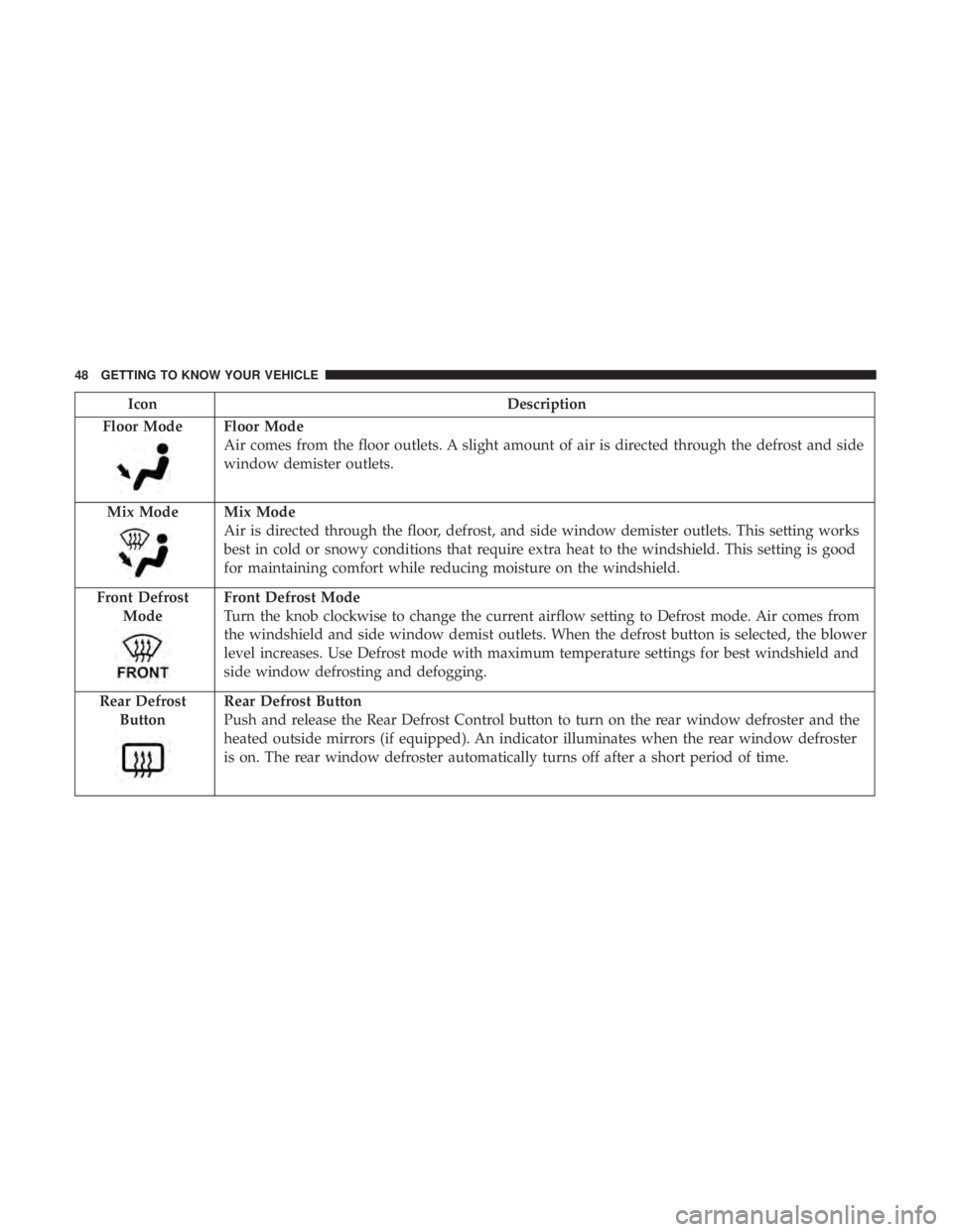
Floor Mode
Floor Mode
Air comes from the floor outlets. A slight amount of air is directed through the defrost and side
window demister outlets.
Mix Mode
Mix Mode
Air is directed through the floor, defrost, and side window demister outlets. This setting works
best in cold or snowy conditions that require extra heat to the windshield. This setting is good
for maintaining comfort while reducing moisture on the windshield.
Front Defrost Mode
Front Defrost Mode
Turn the knob clockwise to change the current airflow setting to Defrost mode. Air comes from
the windshield and side window demist outlets. When the defrost button is selected, the blower
level increases. Use Defrost mode with maximum temperature settings for best windshield and
side window defrosting and defogging.
Rear Defrost Button
Rear Defrost Button
Push and release the Rear Defrost Control button to turn on the rear window defroster and the
heated outside mirrors (if equipped). An indicator illuminates when the rear window defroster
is on. The rear window defroster automatically turns off after a short period of time.
48 GETTING TO KNOW YOUR VEHICLE
Page 84 of 332

Instrument Cluster Display Control Buttons
The driver-interactive instrument cluster display is located
in the center of the instrument cluster.
The system display consists of the following:
•System Status
• Vehicle Information Warning Message Displays
• Personal Settings (Customer Programmable Features)
• Outside Temperature Display •
Trip Computer Functions
• Tire Pressure Monitoring Display
Instrument Cluster Display Control Buttons
Push and release the MENUbutton briefly to access the
instrument cluster display. Push and hold the MENU
button (approximately one second) to return to the main
screen.
Push and release the uparrow button to scroll upward
through the displayed menu and the related options or to
increase the displayed value.
Push and release the downarrow button to scroll down-
ward through the displayed menu and the related options
or to decrease the value displayed.
NOTE: Up anddown arrow buttons activate different
functions according to the following situations:
• To scroll the menu options upwards or downwards.
• To increase or decrease values during settings.
NOTE: When opening one of the front doors, the instru-
ment cluster display will turn on the clock and the miles or
kilometers covered (if equipped) for a few seconds.
Instrument Cluster Display
82 GETTING TO KNOW YOUR INSTRUMENT PANEL
Page 199 of 332
Exterior Bulbs
Bulb Number
Front Low and High Beam Headlamp HIR2LL
Front Parking/Daytime Running Lamps W21/5W
Front Fog Lamps H11LL
Front Side Marker Lamps W3W
Front Turn Signal Lamps WY21W
Side Direction Lamps WY5W
Rear Turn Signal Lamps PY21W
Rear Side Marker Lamps W3W
Rear Tail and Stop Lamps P21/5W
Rear Backup Lamps W16W
Center High Mounted Stop Lamp W5W
License Plate Lamps LED (See Authorized Dealer)
NOTE: Numbers refer to commercial bulb types that can be purchased from an authorized dealer.
If a bulb needs to be replaced, visit an authorized dealer or refer to the applicable Service Manual.
Replacing Exterior Bulbs
Headlamps Low Beam And High Beam
1. Remove the plastic cap from the back of the headlamp housing. 2. Rotate the bulb counter-clockwise.
3. Remove the bulb and replace as needed.
4. Install the bulb and rotate clockwise to lock in place.
5. Reinstall the plastic cap.
7
IN CASE OF EMERGENCY 197
Page 200 of 332

Front Turn Signal, Parking And Daytime Running
Lamps
1. Turn the steering wheel completely to the left or right.
2. Open the wheel housing access door.
3. Remove the plastic cap from the back of the lamphousing.
4. Rotate bulb/socket counter-clockwise.
5. Remove the bulb and replace as needed. 6. Install the bulb into socket, and rotate bulb/socket
clockwise into lamp locking it in place.
7. Reinstall the plastic cap.
Front Fog Lamps
To replace the front fog lights, see an authorized dealer.
Front/Rear Side Marker Lamps
1. Remove portion of the wheel liner to allow hand access to side marker lamp.
2. Rotate the bulb socket counterclockwise, and remove the bulb and socket assembly from the housing.
3. Pull the bulb from the socket and insert the replacement bulb.
4. Install the bulb and socket assembly into the housing, and rotate the socket clockwise to lock it in place.
5. Reinstall the wheel liner.
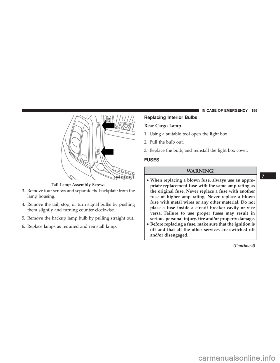
Rear Tail, Stop, Backup And Turn Signal Lamps
1. Open the liftgate.
2. Remove the two screws and remove the tail lamp assembly.
Wheel Housing Access Door
198 IN CASE OF EMERGENCY
Page 201 of 332

3. Remove four screws and separate the backplate from thelamp housing.
4. Remove the tail, stop, or turn signal bulbs by pushing them slightly and turning counter-clockwise.
5. Remove the backup lamp bulb by pulling straight out.
6. Replace lamps as required and reinstall lamp.
Replacing Interior Bulbs
Rear Cargo Lamp
1. Using a suitable tool open the light box.
2. Pull the bulb out.
3. Replace the bulb, and reinstall the light box cover.
FUSES
WARNING!
• When replacing a blown fuse, always use an appro-
priate replacement fuse with the same amp rating as
the original fuse. Never replace a fuse with another
fuse of higher amp rating. Never replace a blown
fuse with metal wires or any other material. Do not
place a fuse inside a circuit breaker cavity or vice
versa. Failure to use proper fuses may result in
serious personal injury, fire and/or property damage.
• Before replacing a fuse, make sure that the ignition is
off and that all the other services are switched off
and/or disengaged.
(Continued)
Tail Lamp Assembly Screws
7
IN CASE OF EMERGENCY 199
Page 296 of 332
Voice
After pressing the “Voice” button on the touchscreen, the
following settings will be available:
Setting NameSelectable Options
Voice Response Length Brief Long
Show Command List AlwaysWith Help Never
Clock & Date
After pressing the “Clock & Date” button on the touch-
screen, the following settings will be available:
Setting Name Selectable Options
Set Time and Format 12 hour24 hour
NOTE: Press the corresponding arrow above and below the current time to adjust, then select “AM” or “PM.”
Show Time Status OnOff
Set Date Set Date
NOTE: Press the corresponding arrows above and below the current date to adjust.
Sync Time — If Equipped OnOff
NOTE: When in the “Sync Time” display, you may sync the time with GPS.
294 MULTIMEDIA