Page 94 of 496
WARNING!
•Be certain that the seatback is securely locked into
position. If the seatback is not securely locked into
position, the seat will not provide the proper stabil-
ity for child seats and/or passengers. An improperly
latched seat could cause serious injury.
• The cargo area in the rear of the vehicle (with the rear
seatbacks in the locked-up or folded down position)
should not be used as a play area by children when
the vehicle is in motion. They could be seriously
injured in a collision. Children should be seated and
using the proper restraint system.
• To help protect against personal injury, passengers
should not be seated in the rear cargo area. The rear
cargo space is intended for load carrying purposes
only, not for passengers, who should sit in seats and
use seat belts.
The weight and position of cargo and passengers can
change the vehicle center of gravity and vehicle han-
dling. To avoid loss of control resulting in personal
injury, follow these guidelines for loading your ve-
hicle:
(Continued)
WARNING! (Continued)
•Always place cargo evenly on the cargo floor. Put
heavier objects as low and as far forward as possible.
• Place as much cargo as possible in front of the rear
axle. Too much weight or improperly placed weight
over or behind the rear axle can cause the rear of the
vehicle to sway.
•
Do not pile luggage or cargo higher than the top of the
seatback. This could impair visibility or become a
dangerous projectile in a sudden stop or collision.
GARAGE DOOR OPENER — IF EQUIPPED
HomeLink replaces up to three hand-held transmitters that
operate devices such as garage door openers, motorized
gates, lighting or home security systems. The HomeLink
unit is powered by your vehicle’s battery.
The HomeLink buttons, located on either the overhead
console, headliner or sunvisor, designate the three different
HomeLink channels. The HomeLink indicator is located
above the center button.
92 GETTING TO KNOW YOUR VEHICLE
Page 100 of 496
Troubleshooting Tips
If you are having trouble programming HomeLink, here
are some of the most common solutions:
•Replace the battery in the Garage Door Opener hand-
held transmitter.
• Push the LEARN button on the Garage Door Opener to
complete the training for a Rolling Code.
• Did you unplug the device for programming and re-
member to plug it back in?
If you have any problems, or require assistance, please call
toll-free 1-800-355-3515 or, on the Internet at
HomeLink.com for information or assistance.
WARNING!
• Vehicle exhaust contains carbon monoxide, a danger-
ous gas. Do not run your vehicle in the garage while
programming the transceiver. Exhaust gas can cause
serious injury or death.
•
Your motorized door or gate will open and close while
you are programming the universal transceiver. Do not
program the transceiver if people, pets or other objects
(Continued)
WARNING! (Continued)
are in the path of the door or gate. Only use this
transceiver with a garage door opener that has a “stop
and reverse” feature as required by Federal safety
standards. This includes most garage door opener mod-
els manufactured after 1982. Do not use a garage door
opener without these safety features. Call toll-free
1-800-355-3515 or, on the Internet at HomeLink.com for
safety information or assistance.
General Information
The following regulatory statement applies to all Radio
Frequency (RF) devices equipped in this vehicle:
This device complies with Part 15 of the FCC Rules and
with Innovation, Science and Economic Development
Canada license-exempt RSS standard(s). Operation is sub-
ject to the following two conditions:
1. This device may not cause harmful interference, and
2. This device must accept any interference received, in-
cluding interference that may cause undesired opera-
tion.
98 GETTING TO KNOW YOUR VEHICLE
Page 102 of 496
lower storage compartment is made for larger items, like
tissue boxes. In addition, the 12 volt power outlet, USB and
Aux jack are located here.
WARNING!
Do not operate this vehicle with a console compart-
ment lid in the open position. Driving with the console
compartment lid open may result in injury in a colli-
sion.
Door Storage
The door panels contain storage areas.
Upper Storage TrayFront Door Trim Storage
100 GETTING TO KNOW YOUR VEHICLE
Page 105 of 496
NOTE:
•All accessories connected to the “battery” powered
outlets should be removed or turned off when the
vehicle is not in use to protect the battery against
discharge.
The front power outlet is located inside the storage area on
the center stack of the instrument panel.WARNING!
Do not place ashes inside the cubby bin located on the
center console on vehicles not equipped with the ash
receiver tray. A fire leading to bodily injury could
result.
In addition to the front power outlet, there is also a power
outlet located in the storage area of the center console.
Front Power Outlet
Center Console Power Outlet
3
GETTING TO KNOW YOUR VEHICLE 103
Page 106 of 496
NOTE:If the Media Hub is in use, do not exceed the
maximum power of 100 Watts (8 Amps) for the center
console power outlet. When the Media Hub is not in use,
the outlet can deliver up to 160 Watts (13 Amps). If the
power rating is exceeded, the fuse protecting the system
needs to be replaced. NOTE:
The instrument panel power outlet and dual rear
console USB ports can be changed to “battery” powered all
the time by moving the #12 20 Amp fuse from “IGN” to
“B+”. Refer to “Fuses” in “In Case Of Emergency” for
further information.
WARNING!
To avoid serious injury or death:
• Only devices designed for use in this type of outlet
should be inserted into any 12 Volt outlet.
• Do not touch with wet hands.
• Close the lid when not in use and while driving the
vehicle.
• If this outlet is mishandled, it may cause an electric
shock and failure.
CAUTION!
•Many accessories that can be plugged in draw power from
the vehicle’s battery even when not in use (i.e., cellular
phones, etc.). Eventually, if plugged in long enough, the
vehicle’s battery will discharge sufficiently to degrade
battery life and/or prevent the engine from starting.
(Continued)
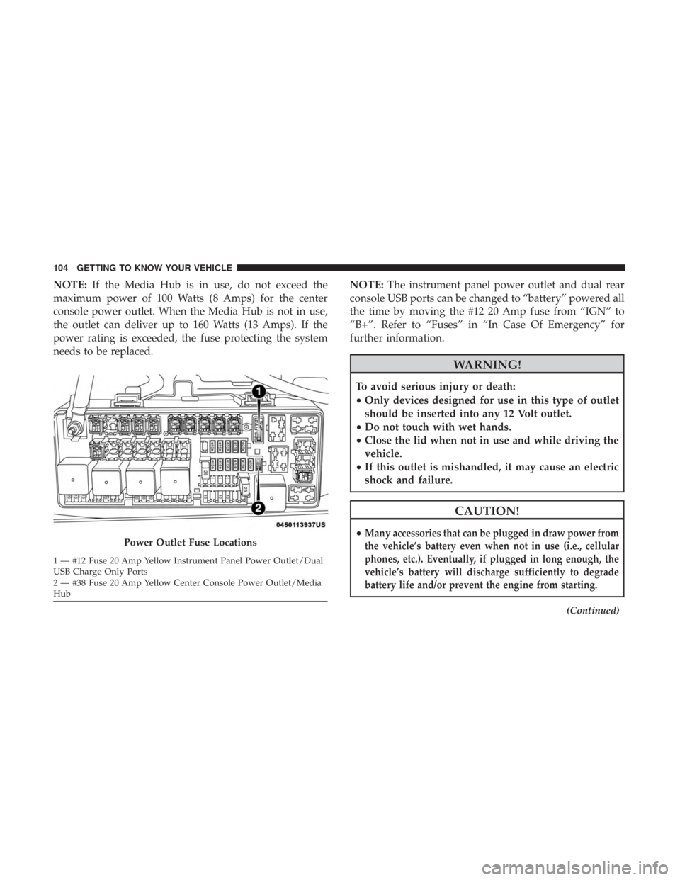
Power Outlet Fuse Locations
1 — #12 Fuse 20 Amp Yellow Instrument Panel Power Outlet/Dual
USB Charge Only Ports
2 — #38 Fuse 20 Amp Yellow Center Console Power Outlet/Media
Hub 104 GETTING TO KNOW YOUR VEHICLE
Page 109 of 496
GETTING TO KNOW YOUR INSTRUMENT PANEL
CONTENTS
�INSTRUMENT CLUSTER ..................108
▫ Instrument Cluster Descriptions ............108
� INSTRUMENT CLUSTER DISPLAY ...........110
▫ Location And Controls ...................110
▫ Engine Oil Life Reset ....................112
▫ Performance Shift Indicator (PSI) —
If Equipped ...........................113
▫ Instrument Cluster Display Selectable Menu
Items ...............................113
▫ Battery Saver On/Battery Saver Mode Message —
Electrical Load Reduction Actions —
If Equipped ......................... .120
� WARNING LIGHTS AND MESSAGES .........122▫
Red Warning Lights .....................122
▫ Yellow Warning Lights ...................126
▫ Yellow Indicator Lights ...................131
▫ Green Indicator Lights ...................131
▫ White Indicator Lights ...................132
▫ Blue Indicator Lights ....................133
� ONBOARD DIAGNOSTIC SYSTEM — OBD II . . .133
▫ Onboard Diagnostic System (OBD II)
Cybersecurity ........................ .134
� EMISSIONS INSPECTION AND MAINTENANCE
PROGRAMS .......................... .1354
Page 111 of 496
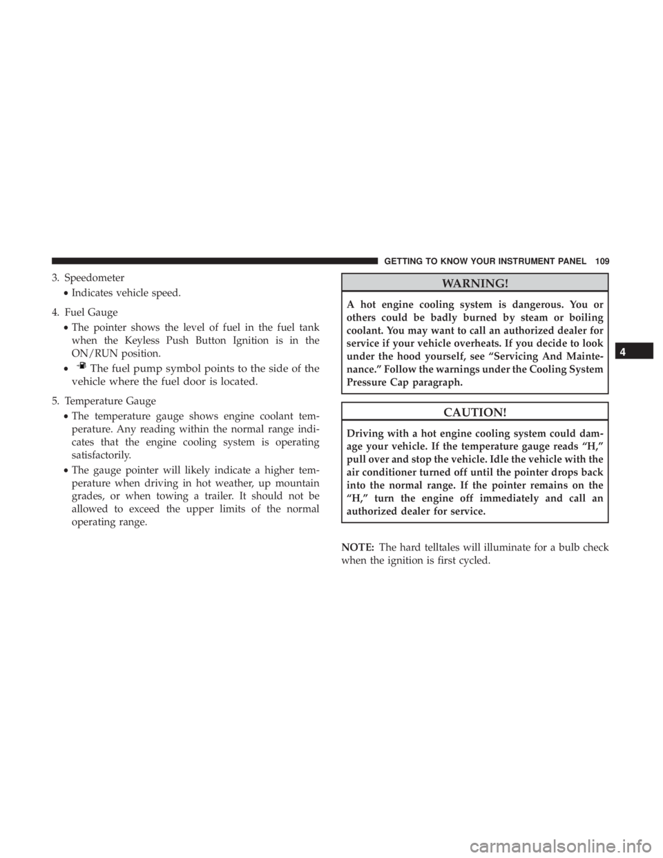
3. Speedometer•Indicates vehicle speed.
4. Fuel Gauge •The pointer shows the level of fuel in the fuel tank
when the Keyless Push Button Ignition is in the
ON/RUN position.
•
The fuel pump symbol points to the side of the
vehicle where the fuel door is located.
5. Temperature Gauge
•The temperature gauge shows engine coolant tem-
perature. Any reading within the normal range indi-
cates that the engine cooling system is operating
satisfactorily.
• The gauge pointer will likely indicate a higher tem-
perature when driving in hot weather, up mountain
grades, or when towing a trailer. It should not be
allowed to exceed the upper limits of the normal
operating range.
WARNING!
A hot engine cooling system is dangerous. You or
others could be badly burned by steam or boiling
coolant. You may want to call an authorized dealer for
service if your vehicle overheats. If you decide to look
under the hood yourself, see “Servicing And Mainte-
nance.” Follow the warnings under the Cooling System
Pressure Cap paragraph.
CAUTION!
Driving with a hot engine cooling system could dam-
age your vehicle. If the temperature gauge reads “H,”
pull over and stop the vehicle. Idle the vehicle with the
air conditioner turned off until the pointer drops back
into the normal range. If the pointer remains on the
“H,” turn the engine off immediately and call an
authorized dealer for service.
NOTE: The hard telltales will illuminate for a bulb check
when the ignition is first cycled.
4
GETTING TO KNOW YOUR INSTRUMENT PANEL 109
Page 112 of 496
INSTRUMENT CLUSTER DISPLAY
Your vehicle will be equipped with an instrument cluster
display, which offers useful information to the driver. With
the ignition in the STOP/OFF mode, opening/closing of a
door will activate the display for viewing, and display the
total miles, or kilometers, in the odometer. Your instrument
cluster display is designed to display important informa-
tion about your vehicle’s systems and features. Using a
driver interactive display located on the instrument panel,
your instrument cluster display can show you how sys-
tems are working and give you warnings when they are
not. The steering wheel mounted controls allow you to
scroll through the main menus and submenus. You can
access the specific information you want and make selec-
tions and adjustments.
Location And Controls
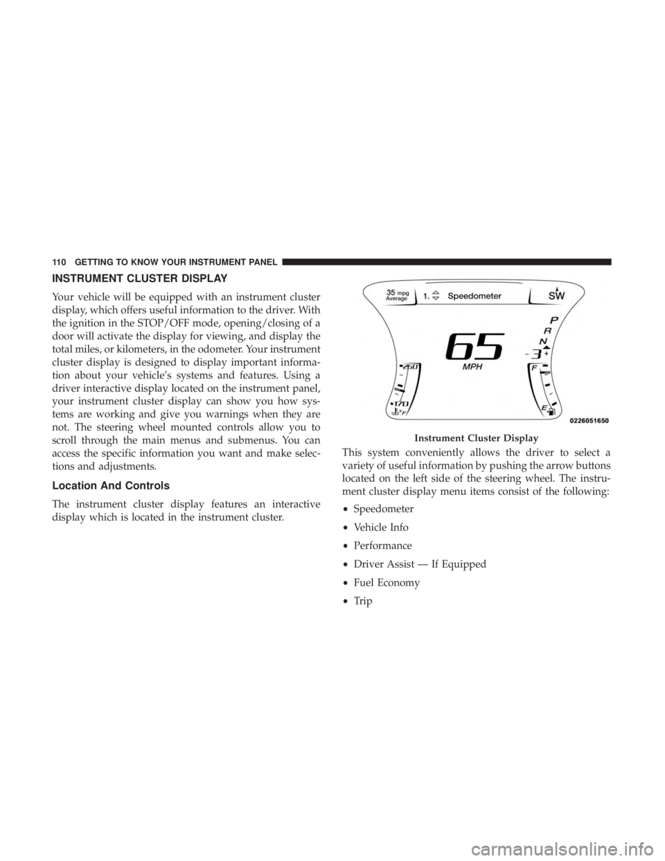
The instrument cluster display features an interactive
display which is located in the instrument cluster.This system conveniently allows the driver to select a
variety of useful information by pushing the arrow buttons
located on the left side of the steering wheel. The instru-
ment cluster display menu items consist of the following:
•
Speedometer
• Vehicle Info
• Performance
• Driver Assist — If Equipped
• Fuel Economy
• Trip
Instrument Cluster Display
110 GETTING TO KNOW YOUR INSTRUMENT PANEL