Page 3 of 496

TABLE OF CONTENTSSECTIONPAGE
1INTRODUCTION
...................................................................3
2GRAPHICAL TABLE OF CONTENTS
......................................................7
3GETTING TO KNOW YOUR VEHICLE
...................................................13
4GETTING TO KNOW YOUR INSTRUMENT PANEL
.........................................107
5SAFETY
........................................................................\
137
6STARTINGANDOPERATING.........................................................209
7INCASEOFEMERGENCY ...........................................................281
8SERVICING AND MAINTENANCE
.....................................................327
9TECHNICAL SPECIFICATIONS
........................................................385
10MULTIMEDIA ....................................................................397
11CUSTOMER ASSISTANCE
............................................................471
12INDEX........................................................................\
..477
1
2
3
4
5
6
7
8
9
10 11
12
Page 7 of 496

HOW TO USE THIS MANUAL
Essential Information
Consult the Table of Contents to determine which section
contains the information you desire.
Since the specification of your vehicle depends on the items
of equipment ordered, certain descriptions and illustra-
tions may differ from your vehicle’s equipment.
The detailed index at the back of this Owner’s Manual
contains a complete listing of all subjects.
Symbols
Some vehicle components have colored labels whose sym-
bols indicate precautions to be observed when using this
component. Refer to “Warning Lights and Messages” in
“Getting To Know Your Instrument Panel” for further
information on the symbols used in your vehicle.
WARNINGS AND CAUTIONS
This Owner ’s Manual containsWARNINGSagainst operat-
ing procedures that could result in a collision, bodily injury
and/or death. It also contains CAUTIONSagainst procedures
that could result in damage to your vehicle. If you do not read
this entire Owner ’s Manual, you may miss important infor-
mation. Observe all Warnings and Cautions.
VEHICLE MODIFICATIONS/ALTERATIONS
WARNING!
Any modifications or alterations to this vehicle could
seriously affect its roadworthiness and safety and may
lead to a collision resulting in serious injury or death.
WARNING!
To prevent SERIOUS INJURY or DEATH when using
“Track-Use” parts and equipment:
• NEVER use any “Track-Use” equipment on public
roads. FCA US LLC does not authorize the use of
“Track-Use” equipment on public roads.
• The intended use of “Track-Use” parts is for race
vehicles on race tracks. To help ensure the safety of
the race driver, engineers should supervise the instal-
lation of “Track-Use” parts.
• FCA US LLC does not authorize the installation or
use of any part noted as “Track-Use” on any new
vehicle prior to its first retail sale.
1
INTRODUCTION 5
Page 9 of 496
GRAPHICAL TABLE OF CONTENTS
CONTENTS
�FRONT VIEW ............................8
� REAR VIEW .............................9 �
INSTRUMENT PANEL .....................10
� INTERIOR .............................11
2
Page 12 of 496
INSTRUMENT PANEL
Instrument Panel
1 — Instrument Cluster Display Controls7 — Ignition
2 — Paddle Shifters 8 — Switch Panel
3 — Multifunction Lever (Behind Steering Wheel) 9 — Uconnect System
4 — Headlight Switch (Behind Steering Wheel) 10 — Climate Controls
5 — Instrument Cluster 11 — Front Power Outlet
6 — Speed Controls 10 GRAPHICAL TABLE OF CONTENTS
Page 65 of 496
EXTERIOR LIGHTS
Headlight Switch
The headlight switch is located on the left side of the instrument
panel. This switch controls the operation of the headlights,
parking lights, instrument panel lights, instrument panel light
dimming, interior lights and fog lights (if equipped).
Rotate the headlight switch clockwise to the first detent for
parking light and instrument panel light operation. Rotate
the headlight switch to the second detent for headlight,
parking light and instrument panel light operation. Push
the switch to enable fog lights (if equipped).
Multifunction Lever
The multifunction lever controls the operation of the turn
signals, headlight beam selection and passing lights. The
multifunction lever is located on the left side of the steering
column.
Headlight Switch
Multifunction Lever
3
GETTING TO KNOW YOUR VEHICLE 63
Page 67 of 496

To Deactivate
1. Pull the multifunction lever toward you (or rearward invehicle) to manually deactivate the system (normal
operation of low beams).
2. Push back on the multifunction lever to reactivate the system.
The Automatic High Beams can also be deactivated
through the Uconnect system. Refer to “Uconnect Settings”
in “Multimedia” for further information.
Flash-To-Pass
You can signal another vehicle with your headlights by
lightly pulling the multifunction lever toward you. This
will turn on the high beam headlights until the lever is
released.
NOTE: If the multifunction lever is held in the flash-to pass
position for more than 20 seconds, the high beams will shut
off.
Automatic Headlights
This system automatically turns the headlights on or off
according to ambient light levels. To turn the system on,
rotate the headlight switch counterclockwise to the AUTO position. When the system is on, the headlight time delay
feature is also on. This means the headlights will stay on
for up to 90 seconds after you place the ignition into the
OFF position. The headlight time delay can be pro-
grammed 0/30/60/90 seconds.
Refer to “Uconnect Settings” in “Multimedia” for further
information.
To turn the automatic system off, move the headlight
switch out of the AUTO position.
NOTE:
The engine must be running before the headlights
will come on in the automatic mode.
Parking Lights
Turn the headlight switch knob to the first detent to turn
the parking lights on. This also turns on all instrument
panel lighting.
Headlights On With Wipers
When this feature is active, the headlights will turn on after
the wipers are turned on if the headlight switch is placed in
the AUTO position and programmable feature is set to on.
In addition, the headlights will turn off when the wipers
are turned off if they were turned on by this feature.
3
GETTING TO KNOW YOUR VEHICLE 65
Page 72 of 496
Dimmer Controls
The dimmer control is part of the headlight switch and is
located on the left side of the instrument panel.
With the parking lights or headlights on, rotating the left
dimmer control upward will increase the brightness of the
instrument panel lights and lighted cupholders (if
equipped).Dome Light Position
Rotate the dimmer control completely upward to the
second detent to turn on the interior lights. The interior
lights will remain on when the dimmer control is in this
position.
Interior Light Defeat (Off)
Rotate the instrument panel dimmer control to the extreme
bottom (O) off position. The interior lights will remain off
when the doors are open.
Dimmer Controls
Instrument Panel Dimmer
70 GETTING TO KNOW YOUR VEHICLE
Page 73 of 496

Parade Mode (Daytime Brightness Feature)
Rotate the instrument panel dimmer control upward to the
first detent. This feature brightens all text displays such as
the odometer, instrument cluster display, and radio when
the position lights or headlights are on.
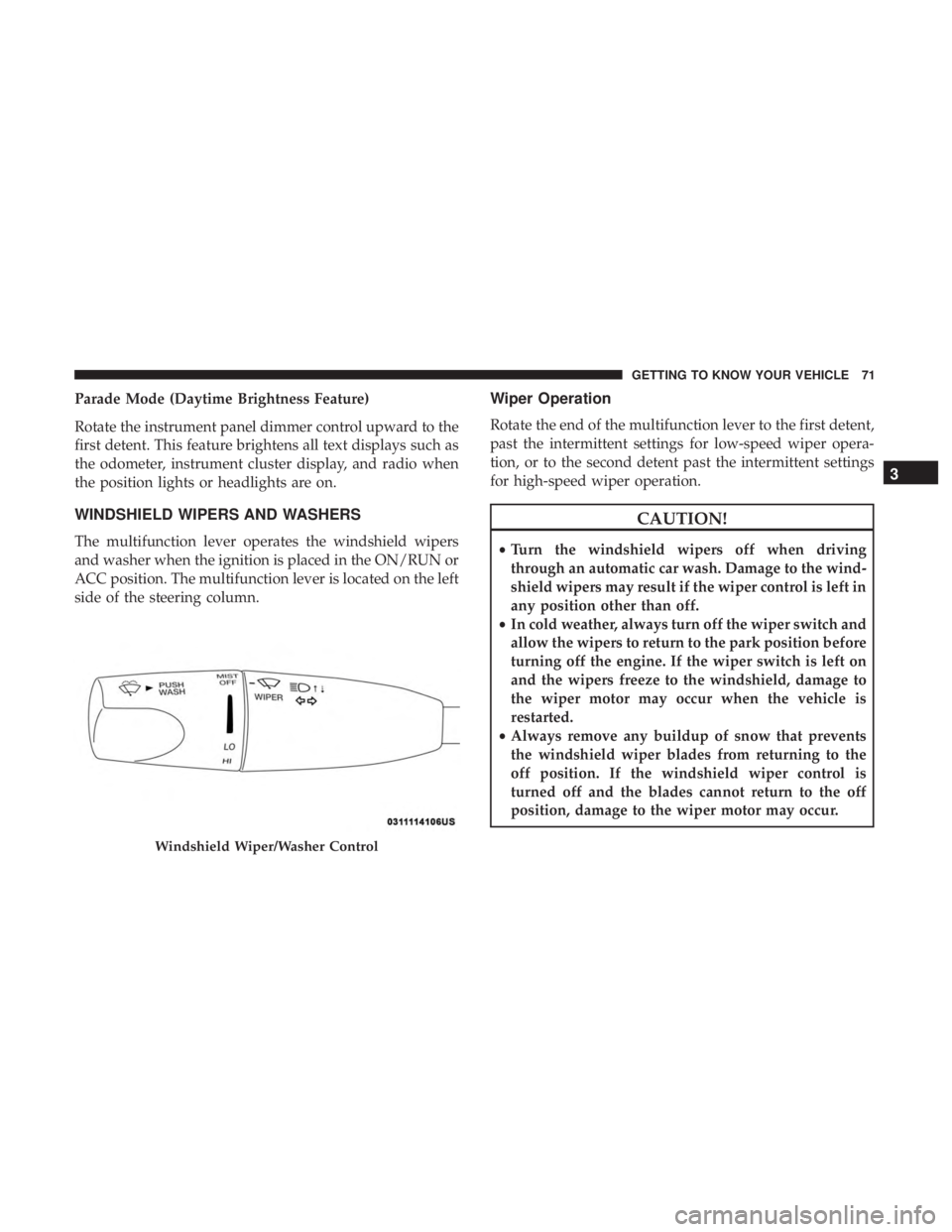
WINDSHIELD WIPERS AND WASHERS
The multifunction lever operates the windshield wipers
and washer when the ignition is placed in the ON/RUN or
ACC position. The multifunction lever is located on the left
side of the steering column.
Wiper Operation
Rotate the end of the multifunction lever to the first detent,
past the intermittent settings for low-speed wiper opera-
tion, or to the second detent past the intermittent settings
for high-speed wiper operation.
CAUTION!
•Turn the windshield wipers off when driving
through an automatic car wash. Damage to the wind-
shield wipers may result if the wiper control is left in
any position other than off.
• In cold weather, always turn off the wiper switch and
allow the wipers to return to the park position before
turning off the engine. If the wiper switch is left on
and the wipers freeze to the windshield, damage to
the wiper motor may occur when the vehicle is
restarted.
• Always remove any buildup of snow that prevents
the windshield wiper blades from returning to the
off position. If the windshield wiper control is
turned off and the blades cannot return to the off
position, damage to the wiper motor may occur.
Windshield Wiper/Washer Control
3
GETTING TO KNOW YOUR VEHICLE 71