Page 71 of 500

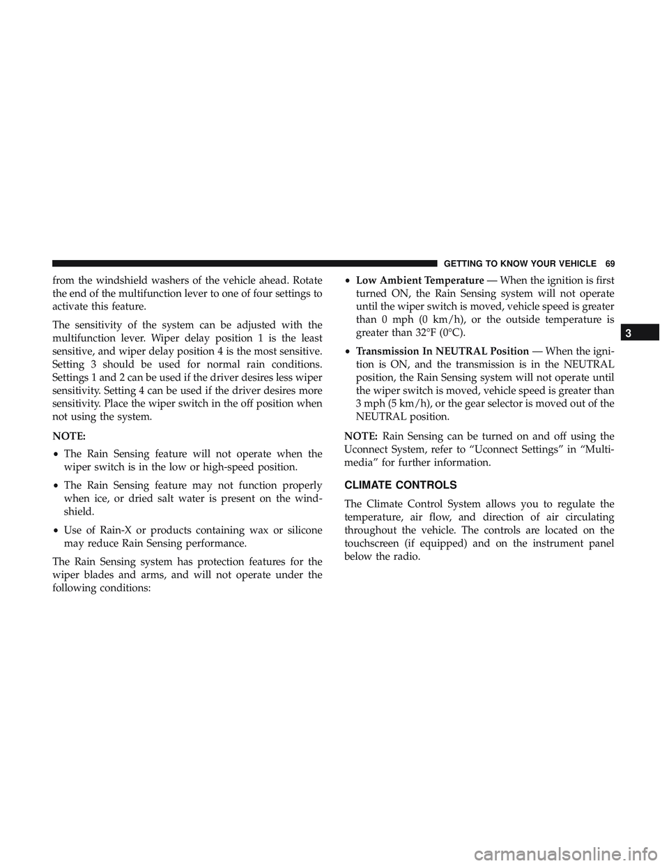
from the windshield washers of the vehicle ahead. Rotate
the end of the multifunction lever to one of four settings to
activate this feature.
The sensitivity of the system can be adjusted with the
multifunction lever. Wiper delay position 1 is the least
sensitive, and wiper delay position 4 is the most sensitive.
Setting 3 should be used for normal rain conditions.
Settings 1 and 2 can be used if the driver desires less wiper
sensitivity. Setting 4 can be used if the driver desires more
sensitivity. Place the wiper switch in the off position when
not using the system.
NOTE:
•The Rain Sensing feature will not operate when the
wiper switch is in the low or high-speed position.
• The Rain Sensing feature may not function properly
when ice, or dried salt water is present on the wind-
shield.
• Use of Rain-X or products containing wax or silicone
may reduce Rain Sensing performance.
The Rain Sensing system has protection features for the
wiper blades and arms, and will not operate under the
following conditions: •
Low Ambient Temperature — When the ignition is first
turned ON, the Rain Sensing system will not operate
until the wiper switch is moved, vehicle speed is greater
than 0 mph (0 km/h), or the outside temperature is
greater than 32°F (0°C).
• Transmission In NEUTRAL Position — When the igni-
tion is ON, and the transmission is in the NEUTRAL
position, the Rain Sensing system will not operate until
the wiper switch is moved, vehicle speed is greater than
3 mph (5 km/h), or the gear selector is moved out of the
NEUTRAL position.
NOTE: Rain Sensing can be turned on and off using the
Uconnect System, refer to “Uconnect Settings” in “Multi-
media” for further information.
CLIMATE CONTROLS
The Climate Control System allows you to regulate the
temperature, air flow, and direction of air circulating
throughout the vehicle. The controls are located on the
touchscreen (if equipped) and on the instrument panel
below the radio.
3
GETTING TO KNOW YOUR VEHICLE 69
Page 75 of 500

IconDescription
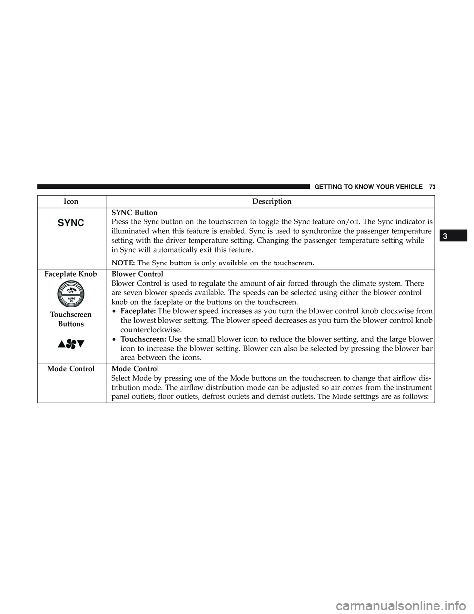
SYNC Button
Press the Sync button on the touchscreen to toggle the Sync feature on/off. The Sync indicator is
illuminated when this feature is enabled. Sync is used to synchronize the passenger temperature
setting with the driver temperature setting. Changing the passenger temperature setting while
in Sync will automatically exit this feature.
NOTE:The Sync button is only available on the touchscreen.
Faceplate Knob
Touchscreen Buttons
Blower Control
Blower Control is used to regulate the amount of air forced through the climate system. There
are seven blower speeds available. The speeds can be selected using either the blower control
knob on the faceplate or the buttons on the touchscreen.
• Faceplate: The blower speed increases as you turn the blower control knob clockwise from
the lowest blower setting. The blower speed decreases as you turn the blower control knob
counterclockwise.
• Touchscreen: Use the small blower icon to reduce the blower setting, and the large blower
icon to increase the blower setting. Blower can also be selected by pressing the blower bar
area between the icons.
Mode Control Mode Control Select Mode by pressing one of the Mode buttons on the touchscreen to change that airflow dis-
tribution mode. The airflow distribution mode can be adjusted so air comes from the instrument
panel outlets, floor outlets, defrost outlets and demist outlets. The Mode settings are as follows:
3
GETTING TO KNOW YOUR VEHICLE 73
Page 76 of 500

IconDescription
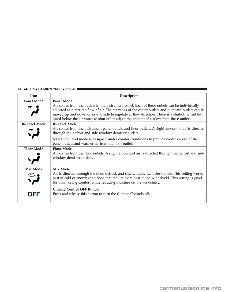
Panel Mode
Panel Mode
Air comes from the outlets in the instrument panel. Each of these outlets can be individually
adjusted to direct the flow of air. The air vanes of the center outlets and outboard outlets can be
moved up and down or side to side to regulate airflow direction. There is a shut-off wheel lo-
cated below the air vanes to shut off or adjust the amount of airflow from these outlets.
Bi-Level Mode
Bi-Level Mode
Air comes from the instrument panel outlets and floor outlets. A slight amount of air is directed
through the defrost and side window demister outlets.
NOTE: Bi-Level mode is designed under comfort conditions to provide cooler air out of the
panel outlets and warmer air from the floor outlets.
Floor Mode
Floor Mode
Air comes from the floor outlets. A slight amount of air is directed through the defrost and side
window demister outlets.
Mix Mode
Mix Mode
Air is directed through the floor, defrost, and side window demister outlets. This setting works
best in cold or snowy conditions that require extra heat to the windshield. This setting is good
for maintaining comfort while reducing moisture on the windshield.
Climate Control OFF Button
Press and release this button to turn the Climate Controls off.
74 GETTING TO KNOW YOUR VEHICLE
Page 84 of 500
NOTE:If three consecutive sunroof close attempts result in
Pinch Protect reversals, Pinch Protect will disable and the
sunroof must be closed in Manual Mode.
Sunroof Maintenance
Use only a non-abrasive cleaner and a soft cloth to clean the
glass panel.
Ignition Off Operation
NOTE:
• The power sunroof switch can remain active in Acces-
sory Delay for up to approximately 10 minutes after the
vehicle’s ignition is placed to the OFF position. Opening
either front door will cancel this feature.
• This feature is programmable using the Uconnect Sys-
tem. Refer to “Uconnect Settings” in “Multimedia” for
further information.
HOOD
To Open The Hood
Two latches must be released to open the hood.
1. Pull the hood release lever located under the left side of
the instrument panel.
Hood Release Lever
82 GETTING TO KNOW YOUR VEHICLE
Page 86 of 500

CAUTION!
To prevent possible damage, do not slam the hood to
close it. Lower hood to approximately 12 inches (30 cm)
and drop the hood to close. Make sure hood is fully
closed for both latches. Never drive vehicle unless
hood is fully closed, with both latches engaged.
TRUNK
Opening
The trunk can be opened from inside the vehicle using the
power trunk button located on the instrument panel to the
left of the steering wheel.
The trunk lid can be released from outside the vehicle by
pushing the trunk button on the key fob twice within five
seconds or by using the external release switch located on
the underside of the decklid overhang. The release feature
will function only when the vehicle is in the unlock
condition.
With the ignition in the ON/RUN position, the trunk open
symbol will display in the instrument cluster indicating
that the trunk is open. The odometer display will reappear
once the trunk is closed.With the ignition in the OFF position, the trunk open
symbol will display until the trunk is closed.
NOTE:
Refer to “Keyless Enter-N-Go — Passive Entry” in
”Doors” in “Getting To Know Your Vehicle” for further
information on trunk operation with the Passive Entry
feature.
Opening From Inside The Vehicle
Interior Power Trunk Release
The trunk can be opened from inside the
vehicle using the power trunk release
button located on the instrument panel
to the left of the steering wheel.
NOTE:The transmission must be in
PARK before the button will operate.
Opening From Outside The Vehicle
To Unlock/Open The Trunk
The trunk may be unlocked/opened using either of the
following methods:
• Key Fob Trunk Release Button
• Passive Entry Button
Power Trunk
Release
84 GETTING TO KNOW YOUR VEHICLE
Page 95 of 500
INTERNAL EQUIPMENT
Storage
Glove Compartment
The glove compartment is located on the passenger side of
the instrument panel.
To open the glove compartment, pull the release handle.
Glove Compartment
Opened Glove Compartment
3
GETTING TO KNOW YOUR VEHICLE 93
Page 98 of 500
These power outlets can also operate a conventional cigar
lighter unit.
The front power outlet is located next to the storage area on
the integrated center stack of the instrument panel.
NOTE:
•The front integrated center stack power outlet can be
changed from switched “ignition” to constant “battery”
powered all the time by moving the integrated center
stack fuse #12 in the Rear Power Distribution Center
from fuse location “IGN” to “B+.” Refer to “Fuses” in
“In Case Of Emergency.” In addition to the front center stack power outlet, there is
also a power outlet located in the center console to the left
of the media hub.
NOTE:
All accessories connected to these powered outlets
should be removed or turned off when the vehicle is not in
use to protect the battery against discharge.
Power Outlet — Integrated Center Stack Front
Power Outlet — Center Console
96 GETTING TO KNOW YOUR VEHICLE
Page 103 of 500

GETTING TO KNOW YOUR INSTRUMENT PANEL
CONTENTS
�INSTRUMENT CLUSTER ..................102
▫ Instrument Cluster Descriptions .............104
� INSTRUMENT CLUSTER DISPLAY ...........105
▫ Location And Controls ...................105
▫ Engine Oil Life Reset ....................107
▫ Performance Shift Indicator (PSI) —
If Equipped .......................... .108
▫ Instrument Cluster Display Selectable Menu
Items ...............................108
▫ Battery Saver On/Battery Saver Mode Message —
Electrical Load Reduction Actions
— If Equipped ........................115 �
WARNING LIGHTS AND MESSAGES .........117
▫ Red Warning Lights .....................117
▫ Yellow Warning Lights ...................122
▫ Yellow Indicator Lights ...................126
▫ Green Indicator Lights ...................126
▫ White Indicator Lights ...................127
▫ Blue Indicator Lights ....................128
� ONBOARD DIAGNOSTIC SYSTEM — OBD II . . .128
▫ Onboard Diagnostic System (OBD II)
Cybersecurity ........................ .129
� EMISSIONS INSPECTION AND MAINTENANCE
PROGRAMS .......................... .1304