Page 300 of 500

CAUTION!
•When installing the power distribution center cover,
it is important to ensure the cover is properly posi-
tioned and fully latched. Failure to do so may allow
water to get into the power distribution center and
possibly result in an electrical system failure.
(Continued)
CAUTION! (Continued)
•When replacing a blown fuse, it is important to use
only a fuse having the correct amperage rating. The
use of a fuse with a rating other than indicated may
result in a dangerous electrical system overload. If a
properly rated fuse continues to blow, it indicates a
problem in the circuit that must be corrected.
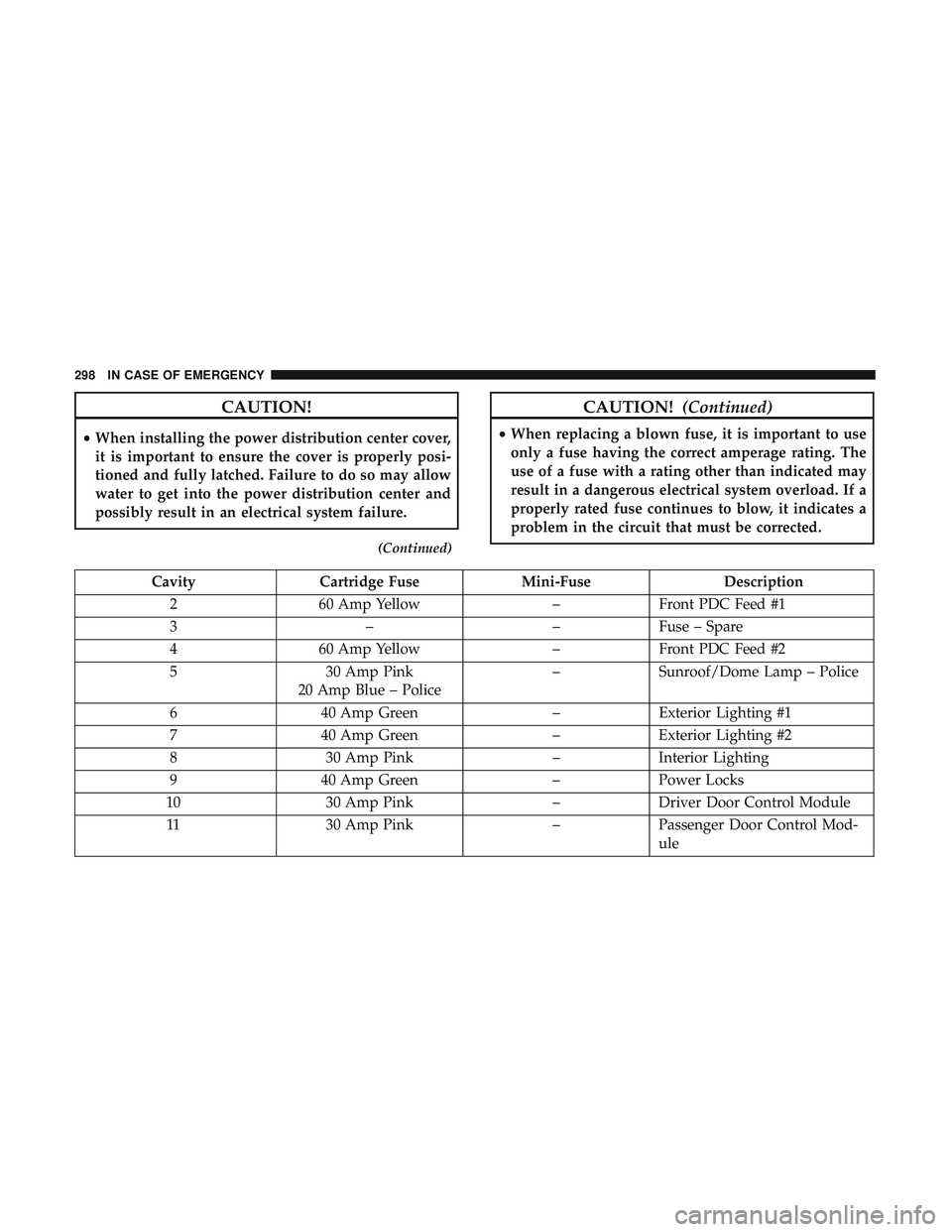
Cavity Cartridge Fuse Mini-Fuse Description
2 60 Amp Yellow –Front PDC Feed #1
3 ––Fuse – Spare
4 60 Amp Yellow –Front PDC Feed #2
5 30 Amp Pink
20 Amp Blue – Police –
Sunroof/Dome Lamp – Police
6 40 Amp Green –Exterior Lighting #1
7 40 Amp Green –Exterior Lighting #2
8 30 Amp Pink –Interior Lighting
9 40 Amp Green –Power Locks
10 30 Amp Pink –Driver Door Control Module
11 30 Amp Pink –Passenger Door Control Mod-
ule
298 IN CASE OF EMERGENCY
Page 301 of 500
CavityCartridge Fuse Mini-Fuse Description
12 –20 Amp Yellow Dual USB Center Console
Rear/Cigar Lighter IP – If
Equipped
15 40 Amp Green –HVAC Blower
16 20 Amp Blue –Left Spot Lamp – Police
17 20 Amp Blue –Right Spot Lamp – Police
18 30 Amp Pink –Mod Network Interface –
Police
19 ––Fuse – Spare
20 ––Fuse – Spare
21 30 Amp Pink –Fuel Pump (Non 6.2L SRT HO)
22 –5 Amp Tan Cyber Gateway Mod
23 –10 Amp Red Fuel Door – If Equipped/
Diagnostic Port
24 –10 Amp Red Integrated Center Stack
25 –10 Amp Red Tire Pressure Monitor
26 –15 Amp Blue Cygnus Transmission Module
(Charger/300) / Electronic
Shift Module (Charger/300)
27 –25 Amp Clear Amplifier – If Equipped
31 –25 Amp Breaker Power Seats – If Equipped
7
IN CASE OF EMERGENCY 299
Page 302 of 500
CavityCartridge Fuse Mini-Fuse Description
32 –15 Amp Blue HVAC Module/Cluster
33 –15 Amp Blue Ignition Switch/RF Hub
Module/Steering Column Lock
(300) – If Equipped
34 –10 Amp Red Steering Column Module/
Clock (300)
35 –5 Amp Tan Battery Sensor
36 –15 Amp Blue Electronic Exhaust Valve – If
Equipped
37 –20 Amp Yellow Radio
38 –20 Amp Yellow Power Outlet Inside Arm
Rest/Console Media Hub
40 30 Amp Pink –Fuel Pump (6.2L SRT HO – If
Equipped)
41 30 Amp Pink –Fuel Pump (6.2L SRT HO – If
Equipped)
42 30 Amp Pink –Rear Defrost
43 –20 Amp Yellow Comfort Seat And Steering
Wheel Module (Heated Steer-
ing Wheel/RR Heated Seats)
300 IN CASE OF EMERGENCY
Page 303 of 500
CavityCartridge Fuse Mini-Fuse Description
44 –10 Amp Red Park Assist / Blind Spot /
Rear View Camera
45 –15 Amp Blue Cluster / Rearview Mirror /
Compass (Charger/300) / Hu-
midity Sensor / Forward Fac-
ing Camera (Lane Departure) /
Cyber Gateway
46 ––Fuse – Spare
47 –10 Amp Red Adaptive Front Lighting / Day
Time Running Lamps – If
Equipped
48 –20 Amp Yellow Active Suspension – (6.4L /
6.2L)
49 ––Fuse – Spare
50 ––Fuse – Spare
51 –20 Amp Yellow Front Heated / Vented Seats –
If Equipped
52 –10 Amp Red Heated Cupholders/Rear
Heated Seat Switches – If
Equipped
53 –10 Amp Red HVAC Module/In Vehicle
Temperature Sensor
7
IN CASE OF EMERGENCY 301
Page 408 of 500

Customer Programmable Features — Uconnect
4C/4C NAV Settings
Press the “Apps” button (if equipped), and then
press the “Settings” button on the touchscreen to dis-
play the menu setting screen. In this mode, the
Uconnect system allows you to access programmable
features that may be equipped such as Language, Dis-
play, Units, Voice, Clock & Date, Safety & Driving
Assistance, Mirrors & Wipers, Lights, Doors & Locks,
Auto-On Comfort, Key Off Options, Audio, Phone/
Bluetooth, SiriusXM Setup, Reset, and System Informa-
tion.
NOTE: Depending on the vehicle’s options, feature set-
tings may vary.
When making a selection, press the button on the touch-
screen to enter the desired mode. Once in the desired
mode, press and release the preferred setting “option” until
a check-mark appears next to the setting, showing that
setting has been selected. Once the setting is complete,
press the “X” button on the touchscreen to close out of the
settings screen. Pressing the up or down arrow button on
the right side of the screen will allow you to toggle up or
down through the available settings.
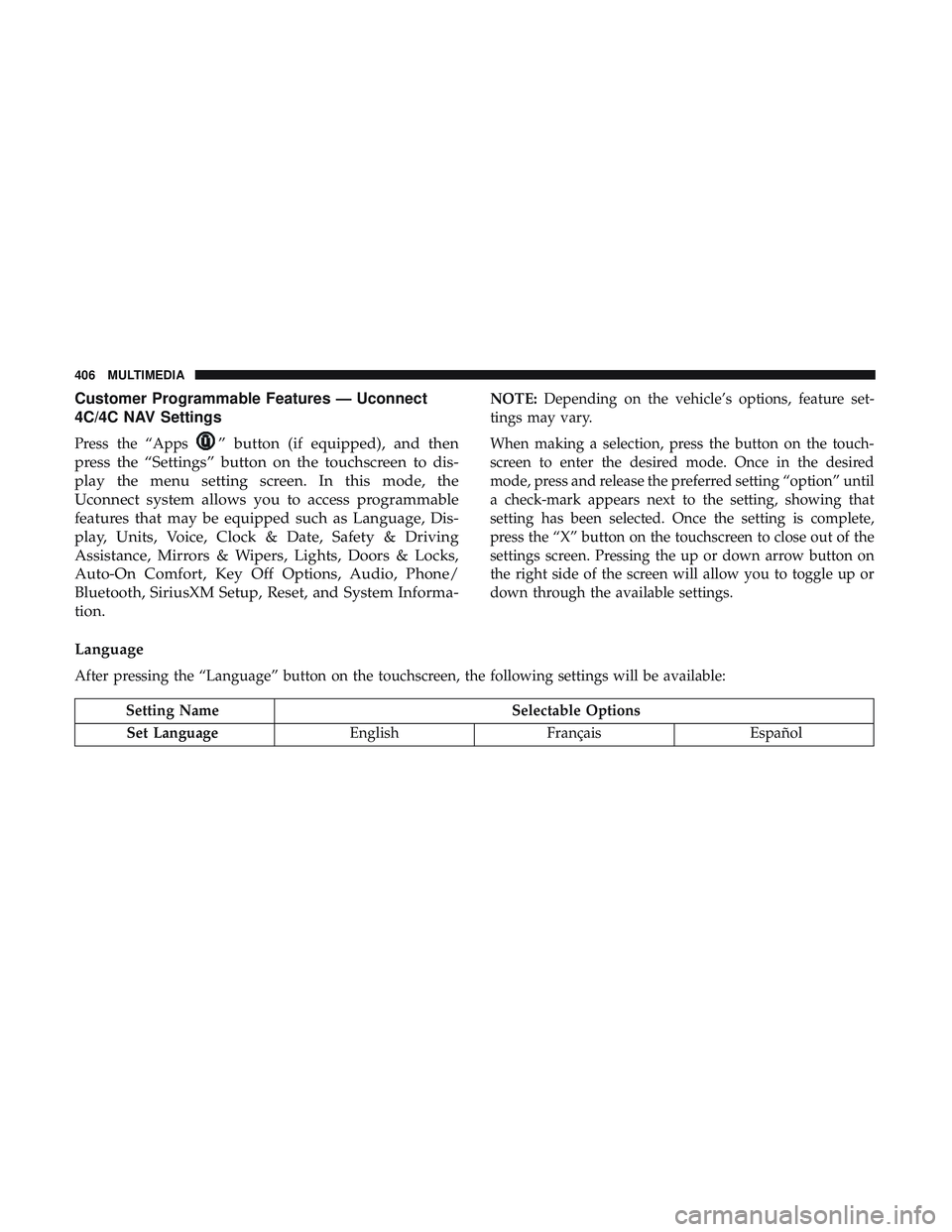
Language
After pressing the “Language” button on the touchscreen, the following settings will be available:
Setting Name Selectable Options
Set Language EnglishFrançais Español
406 MULTIMEDIA
Page 424 of 500
Phone/Bluetooth Settings
After pressing the “Phone/Bluetooth Settings” button on the touchscreen, the following settings will be available:
Setting NameSelectable Options
Do Not Disturb List of Settings
NOTE:
Press “Do Not Disturb” to access the available settings. The following settings are: Auto Reply (both, text, call), Auto
Reply Message (custom, default), and Custom Auto Reply Message (create message). Paired Phones and Audio Sources List Of Paired Phones and Audio Sources
NOTE:
The “Paired Phones and Audio Sources” feature shows which phones and audio sources are paired to the Phone and
Audio Sources Settings system. For further information, refer to the Uconnect Owner ’s Manual Supplement. Smartphone Projection Manager OnOff
NOTE: Pressing “Smartphone Projection Manager” feature allows you to see a list of all connected phones and gives
you the option to determine which phone will be used for projection (Apple CarPlay or Android Auto).
422 MULTIMEDIA
Page 426 of 500
Reset
After pressing the “Reset” button on the touchscreen, the following settings will be available:
Setting NameSelectable Options
Reset App Drawer to Default OKCancel
Restore Apps OKCancel
Restore Settings to Default OKCancel X
NOTE:
When this feature is selected, it will reset all of the radio features to their default settings. To restore the settings to
their default setting, press the “Restore Settings” button on the touchscreen. A pop-up will appear asking �Are you
sure you want to reset your settings to default?”
Clear Personal Data OKCancel X
NOTE:
When this feature is selected, it will remove all personal data including Bluetooth devices and presets. To remove per-
sonal information, press the “Clear Personal Data” button and a pop-up will appear asking �Are you sure you want
to clear all personal data?”
Modem Reset OKCancel
424 MULTIMEDIA
Page 435 of 500
•Steering Wheel Angle:
Steering Wheel Angle utilizes the steering angle sensor to
measure the degree of the steering wheel relative to zero.
The zero degree measurement indicates a steering wheel
straight ahead position. When the steering angle value is
negative, this indicates a turn to the left, and when the
steering angle value is positive, a turn to the right.
The friction circle display shows instantaneous G-Force as
a highlight and previous G-Force as dots within the circle.
The system records previous G-Force for three minutes. If
there are multiple samples at a given point, the color of the
dot will darken from blue to red. Vectors more frequent
will show in red; infrequent vectors will show in blue.Engine
When selected, this screen displays the following values:
• Vehicle Speed
Shows the actual vehicle speed.
Engine
10
MULTIMEDIA 433