Page 293 of 500

3. Remove one fastener on the lower air box to remove andaccess the rear of the headlamp assembly.
4. Reach behind the passenger headlamp assembly.
5. Remove the headlamp cover.
6. Turn the headlamp access cap counterclockwise to re- move.
7. Remove bulb by turn it counter clockwise and discon- nect.
8. Install new bulb by turning it clockwise and reconnect.
9. Reinstall headlamp access cap by turning it clockwise and then reinstall headlamp cover.
10. Reinstall engine air cleaner assembly.
Low Beam Headlamp, High Beam Headlamp —
Models With High Intensity Discharge (HID)
Headlamps — If Equipped
The headlamps are a type of high voltage discharge tube.
High voltage can remain in the circuit even with the
headlamp switch off and the key removed. Because of this,
you should not attempt to service a headlamp bulb
yourself. If a headlamp bulb fails, take your vehicle to an
authorized dealer for service.
WARNING!
A transient high voltage occurs at the bulb sockets of
HID headlamps when the headlamp switch is turned
ON. It may cause serious electrical shock or electrocu-
tion if not serviced properly. See your authorized
dealer for service.
NOTE: On vehicles equipped with HID headlamps, when
the headlamps are turned on, there is a blue hue to the
lamps. This diminishes and becomes more white after
approximately ten seconds, as the system charges.
Front Park/Signature Lamp
The Front Park/Signature function is part of the headlamp
assembly and use LED lamps that are not serviceable
separately. The headlamps must be replaced as an assem-
bly, see your authorized dealer.
Front Turn/DRL Lamp
The Front Turn/DRL function is part of the headlamp
assembly and use LED lamps that are not serviceable
separately. The headlamps must be replaced as an assem-
bly, see your authorized dealer.
7
IN CASE OF EMERGENCY 291
Page 296 of 500

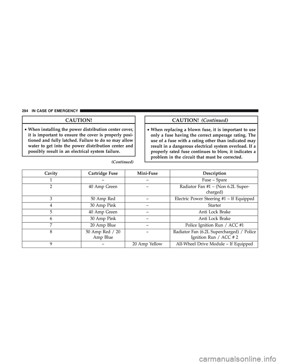
CAUTION!
•When installing the power distribution center cover,
it is important to ensure the cover is properly posi-
tioned and fully latched. Failure to do so may allow
water to get into the power distribution center and
possibly result in an electrical system failure.
(Continued)
CAUTION! (Continued)
•When replacing a blown fuse, it is important to use
only a fuse having the correct amperage rating. The
use of a fuse with a rating other than indicated may
result in a dangerous electrical system overload. If a
properly rated fuse continues to blow, it indicates a
problem in the circuit that must be corrected.
Cavity Cartridge Fuse Mini-Fuse Description
1 –– Fuse – Spare
2 40 Amp Green –Radiator Fan #1 – (Non 6.2L Super-
charged)
3 50 Amp Red –Electric Power Steering #1 – If Equipped
4 30 Amp Pink – Starter
5 40 Amp Green –Anti Lock Brake
6 30 Amp Pink –Anti Lock Brake
7 20 Amp Blue –Police Ignition Run / ACC #1
8 50 Amp Red / 20
Amp Blue –
Radiator Fan (6.2L Supercharged) / Police
Ignition Run / ACC # 2
9 –20 Amp Yellow All-Wheel Drive Module – If Equipped
294 IN CASE OF EMERGENCY
Page 298 of 500
CavityCartridge Fuse Mini-Fuse Description
29 –15 Amp Blue Transmission Control Module (Challenger
/ Charger Police) / Electronic Shift Mod-ule (Challenger)
30 –– Fuse – Spare
31 –25 Amp Clear Engine Module
32 –– Fuse – Spare
33 –– Fuse – Spare
34 –25 Amp Clear Powertrain #1
35 –20 Amp Yellow Powertrain #2
36 –10 Amp Red Anti-Lock Brake Module / Steering Col-
umn Lock Module (300 if equipped)
37 –10 Amp Red Engine Controller / Rad Fan Relays
(Charger/300) / Electric Power SteeringModule (Charger/300) / 5-Speed TCM
38 –10 Amp Red Airbag Module
39 –10 Amp Red EPS (Challenger) / EHPS (Police) / AC
Clutch Relay / Vacuum Pump Relay /Rad Fan Relays (Challenger)
48 –10 Amp Red AWD Module / Front Axle Disconnect –
If Equipped
49 –– Fuse – Spare
296 IN CASE OF EMERGENCY
Page 300 of 500

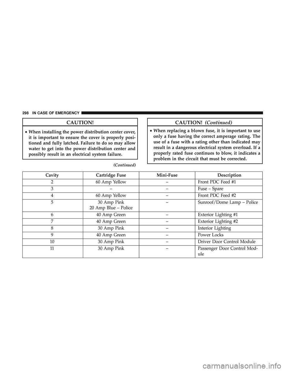
CAUTION!
•When installing the power distribution center cover,
it is important to ensure the cover is properly posi-
tioned and fully latched. Failure to do so may allow
water to get into the power distribution center and
possibly result in an electrical system failure.
(Continued)
CAUTION! (Continued)
•When replacing a blown fuse, it is important to use
only a fuse having the correct amperage rating. The
use of a fuse with a rating other than indicated may
result in a dangerous electrical system overload. If a
properly rated fuse continues to blow, it indicates a
problem in the circuit that must be corrected.
Cavity Cartridge Fuse Mini-Fuse Description
2 60 Amp Yellow –Front PDC Feed #1
3 ––Fuse – Spare
4 60 Amp Yellow –Front PDC Feed #2
5 30 Amp Pink
20 Amp Blue – Police –
Sunroof/Dome Lamp – Police
6 40 Amp Green –Exterior Lighting #1
7 40 Amp Green –Exterior Lighting #2
8 30 Amp Pink –Interior Lighting
9 40 Amp Green –Power Locks
10 30 Amp Pink –Driver Door Control Module
11 30 Amp Pink –Passenger Door Control Mod-
ule
298 IN CASE OF EMERGENCY
Page 302 of 500
CavityCartridge Fuse Mini-Fuse Description
32 –15 Amp Blue HVAC Module/Cluster
33 –15 Amp Blue Ignition Switch/RF Hub
Module/Steering Column Lock
(300) – If Equipped
34 –10 Amp Red Steering Column Module/
Clock (300)
35 –5 Amp Tan Battery Sensor
36 –15 Amp Blue Electronic Exhaust Valve – If
Equipped
37 –20 Amp Yellow Radio
38 –20 Amp Yellow Power Outlet Inside Arm
Rest/Console Media Hub
40 30 Amp Pink –Fuel Pump (6.2L SRT HO – If
Equipped)
41 30 Amp Pink –Fuel Pump (6.2L SRT HO – If
Equipped)
42 30 Amp Pink –Rear Defrost
43 –20 Amp Yellow Comfort Seat And Steering
Wheel Module (Heated Steer-
ing Wheel/RR Heated Seats)
300 IN CASE OF EMERGENCY
Page 313 of 500

5. Position the new Sealant Bottle (1) in the housing so thatthe Sealant Hose (6) aligns with the hose slot in the front
of the housing. Push the bottle into the housing. An
audible click will be heard indicating the bottle is locked
into place.
6. Verify that the cap is installed on the fitting at the end of the Sealant Hose (6) and return the hose to its storage
area (located on the bottom of the air pump).
7. Return the Tire Service Kit to its storage location in the vehicle.
TIRE SERVICE KIT — IF EQUIPPED
Small punctures up to 1/4 inch (6 mm) in the tire tread can
be sealed with Tire Service Kit. Foreign objects (e.g., screws
or nails) should not be removed from the tire. Tire Service
Kit can be used in outside temperatures down to approxi-
mately -4°F (-20°C).
This kit will provide a temporary tire seal, allowing you to
drive your vehicle up to 100 miles (160 km) with a
maximum speed of 50 mph (80 km/h).
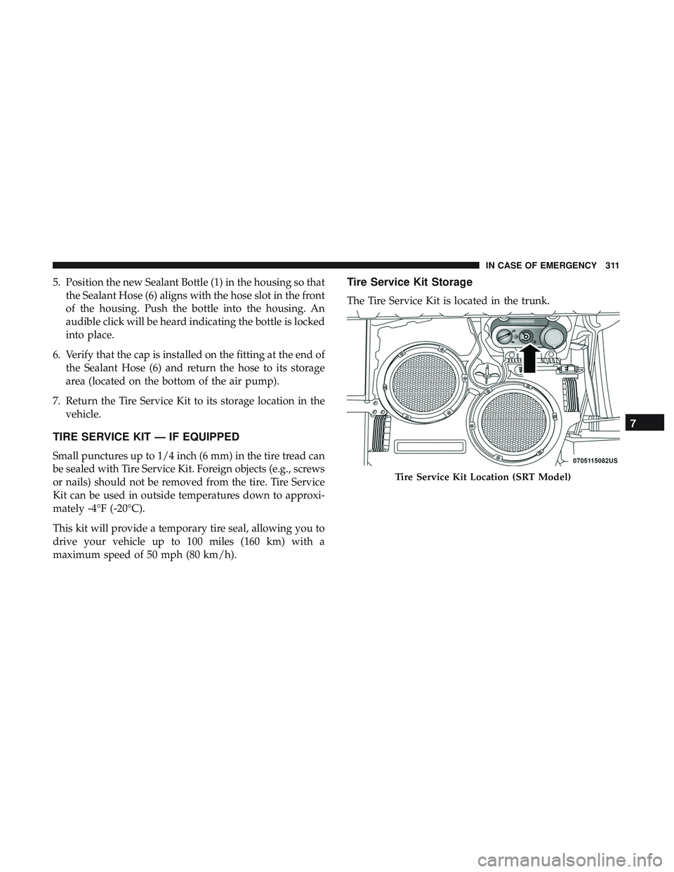
Tire Service Kit Storage
The Tire Service Kit is located in the trunk.
Tire Service Kit Location (SRT Model)
7
IN CASE OF EMERGENCY 311
Page 321 of 500

5. Position the new Sealant Bottle (4) in the housing so thatthe Sealant Hose (3) aligns with the hose slot in the front
of the housing. Push and hold the Sealant Bottle release
button, then push the bottle into the housing by holding
the button. An audible click will be heard indicating the
bottle is locked into place. Release the button.
6. Verify that the cap is installed on the fitting at the end of the Sealant Hose (3) and return the hose to its storage
area (located on top of the housing).
7. Return the Tire Service Kit to its storage location in the vehicle.
JUMP STARTING
If your vehicle has a discharged battery, it can be jump
started using a set of jumper cables and a battery in another
vehicle, or by using a portable battery booster pack. Jump
starting can be dangerous if done improperly, so please
follow the procedures in this section carefully.
WARNING!
Do not attempt jump starting if the battery is frozen. It
could rupture or explode and cause personal injury.
CAUTION!
Do not use a portable battery booster pack or any other
booster source with a system voltage greater than 12
Volts or damage to the battery, starter motor, alternator
or electrical system may occur.
NOTE: When using a portable battery booster pack, follow
the manufacturer’s operating instructions and precautions.
7
IN CASE OF EMERGENCY 319
Page 326 of 500
Follow these steps to use the Manual Park Release:
1. Firmly apply the parking brake.
2. Remove the console storage bin to access the ManualPark Release lever.
3. Using a small screwdriver or similar tool, fish the tether strap up through the opening in the console base.
4. Press and maintain firm pressure on the brake pedal. 5. Insert the screwdriver into the slot in the center of the
lever, and disengage the lever locking tab by pushing it
to the right.
6. While holding the locking tab in the disengaged posi- tion, pull the tether strap to rotate the lever up and
rearward until it locks in place in the vertical position.
The vehicle is now out of PARK and can be moved.
Release the parking brake only when the vehicle is
securely connected to a tow vehicle.
Console Storage Bin
Locking Tab
324 IN CASE OF EMERGENCY