Page 361 of 532
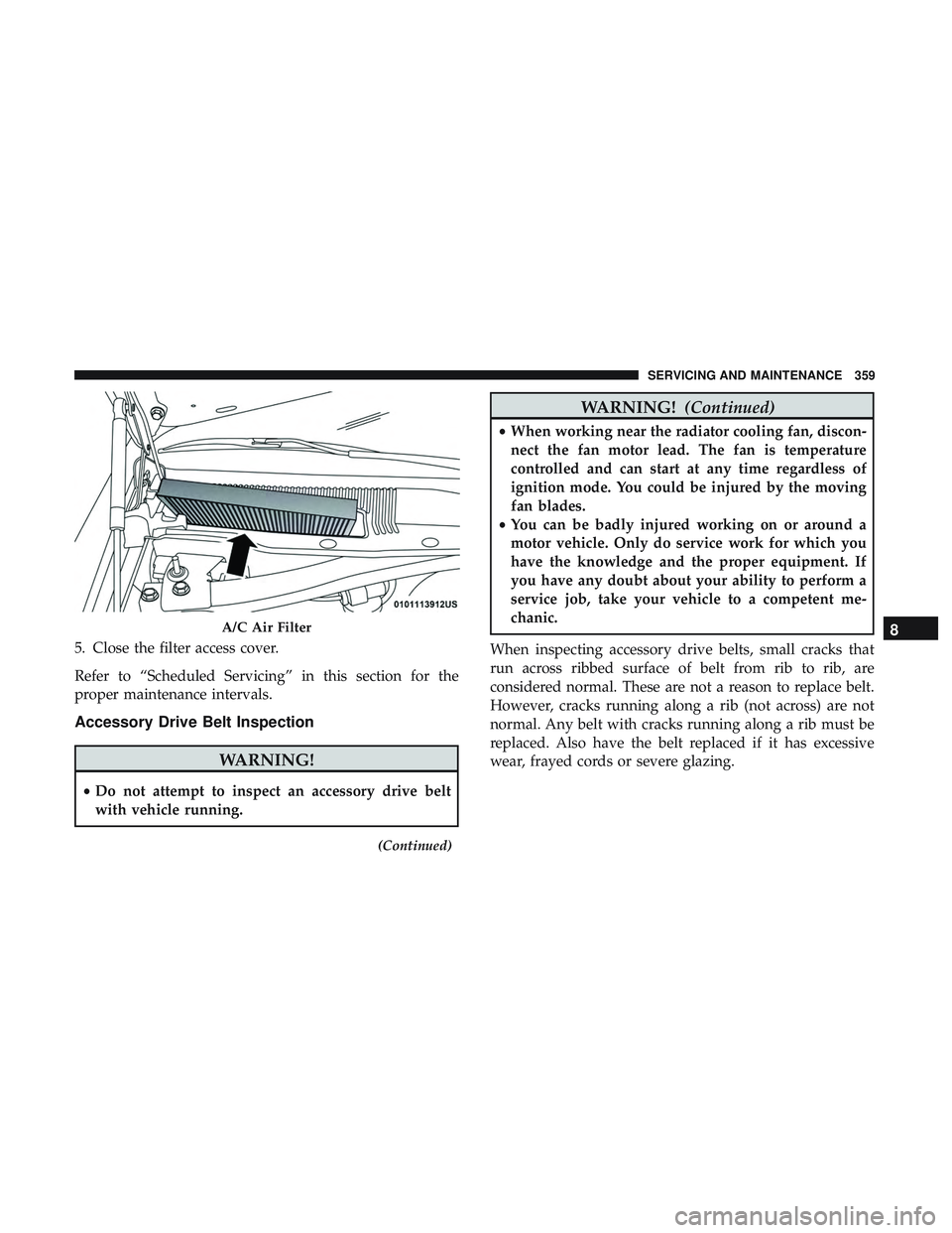
5. Close the filter access cover.
Refer to “Scheduled Servicing” in this section for the
proper maintenance intervals.
Accessory Drive Belt Inspection
WARNING!
•Do not attempt to inspect an accessory drive belt
with vehicle running.
(Continued)
WARNING! (Continued)
•When working near the radiator cooling fan, discon-
nect the fan motor lead. The fan is temperature
controlled and can start at any time regardless of
ignition mode. You could be injured by the moving
fan blades.
• You can be badly injured working on or around a
motor vehicle. Only do service work for which you
have the knowledge and the proper equipment. If
you have any doubt about your ability to perform a
service job, take your vehicle to a competent me-
chanic.
When inspecting accessory drive belts, small cracks that
run across ribbed surface of belt from rib to rib, are
considered normal. These are not a reason to replace belt.
However, cracks running along a rib (not across) are not
normal. Any belt with cracks running along a rib must be
replaced. Also have the belt replaced if it has excessive
wear, frayed cords or severe glazing.
A/C Air Filter8
SERVICING AND MAINTENANCE 359
Page 371 of 532
•Maintain engine coolant (antifreeze) concentration at a
minimum of 50% OAT coolant (conforming to
MS.90032) and distilled water for proper corrosion pro-
tection of your engine which contains aluminum com-
ponents.
• Make sure that the coolant expansion bottle overflow
hoses are not kinked or obstructed.
• Keep the front of the radiator clean. If your vehicle is
equipped with air conditioning, keep the front of the
condenser clean.
• Do not change the thermostat for Summer or Winter
operation. If replacement is ever necessary, install ONLY
the correct type thermostat. Other designs may result in
unsatisfactory engine coolant (antifreeze) performance,
poor gas mileage, and increased emissions.
Brake System
In order to assure brake system performance, all brake
system components should be inspected periodically. Refer
to the “Maintenance Plan” in this section for the proper
maintenance intervals.
WARNING!
Riding the brakes can lead to brake failure and possi-
bly a collision. Driving with your foot resting or riding
on the brake pedal can result in abnormally high brake
temperatures, excessive lining wear, and possible
brake damage. You would not have your full braking
capacity in an emergency.
Fluid Level Check — Brake Master Cylinder
Check the fluid level in the master cylinder immediately if
the brake system warning light indicates system failure.
Check the fluid level in the master cylinder when perform-
ing underhood services.
Clean the top of the master cylinder area before removing
the cap. Add fluid to bring the level up to the top of the
“FULL” mark on the side of the master cylinder reservoir.
Overfilling of fluid is not recommended because it may
cause leaking in the system.
8
SERVICING AND MAINTENANCE 369
Page 373 of 532
Clutch Hydraulic System — Manual Transmission
(If Equipped)
The clutch hydraulic system is fed by a segregated volume of
fluid within the brake system master cylinder reservoir. In
the event of leakage or wear, use only the manufacturer’s
recommended brake fluid. Refer to “Fluids And Lubricants”
in “Technical Specifications” for further information.
Manual Transmission — If Equipped
Fluid Level Check
Check the fluid level by removing the fill plug on the left
side of the transmission. The fluid level should be 1/4 inch
(6.4mm) below the bottom of the fill hole. Add fluid, if
necessary, to maintain the proper level. Refer to “Fluids
And Lubricants” in “Technical Specifications” for further
information.
CAUTION!
Using a transmission fluid other than the manufactur-
er’s recommended fluid may cause deterioration in
transmission shift quality and/or damage to the trans-
mission. Refer to “Fluids And Lubricants” in “Techni-
cal Specifications” for fluid specifications.
Change Transmission Fluid
If contaminated with water, change the fluid immediately.
See your authorized dealer for service.
Refer to the “Maintenance Plan” in this section for the
proper maintenance intervals.
Automatic Transmission — If Equipped
Selection Of Lubricant
It is important to use the proper transmission fluid to
ensure optimum transmission performance and life. Use
only the manufacturer’s specified transmission fluid. Refer
to “Fluids And Lubricants” in “Technical Specifications”
for fluid specifications. It is important to maintain the
transmission fluid at the correct level using the recom-
mended fluid.
NOTE:No chemical flushes should be used in any trans-
mission; only the approved lubricant should be used.
CAUTION!
Using a transmission fluid other than the manufactur-
er ’s recommended fluid may cause deterioration in
(Continued)
8
SERVICING AND MAINTENANCE 371
Page 375 of 532
All Wheel Drive (AWD) — If Equipped
The all wheel drive system consists of a transfer case and
front differential. The exterior surface of these components
should be inspected for evidence of fluid leaks. Confirmed
leaks should be repaired as soon as possible.
The transfer case fluid fill/inspection plug is located in the
middle of the rear housing. To inspect the transfer case
fluid level, remove the fill/inspection plug. The fluid level
should be even with the bottom of the hole. Use this plug
to add fluid as required.
The front differential fill plug is located on the outer cover
near the halfshaft attachment. To inspect the differential
fluid level, remove the fill plug. The fluid level should be
even with or slightly below the bottom of the hole.
Fluid Changes
Refer to “Scheduled Servicing” in “Servicing And Mainte-
nance” for the proper maintenance intervals.
Rear Axle
Fluid Level Check
Checking the fluid level while the vehicle is on level
ground and has been stationary for 15 minutes will im-
prove the accuracy of the fluid level reading.
Check the fluid level by removing the fill plug on the axle.
The fluid level should be 1-2.5 mm below the fill plug. Add
fluid, if necessary, to maintain the proper level. Refer to
“Fluids And Lubricants” in�Servicing And Maintenance”
for further information.
Change Axle Fluid
Refer to “Scheduled Servicing” in “Servicing And Mainte-
nance” for the proper maintenance intervals.
RAISING THE VEHICLE
In the case where it is necessary to raise the vehicle, go to
an authorized dealer or service station.
8
SERVICING AND MAINTENANCE 373
Page 522 of 532
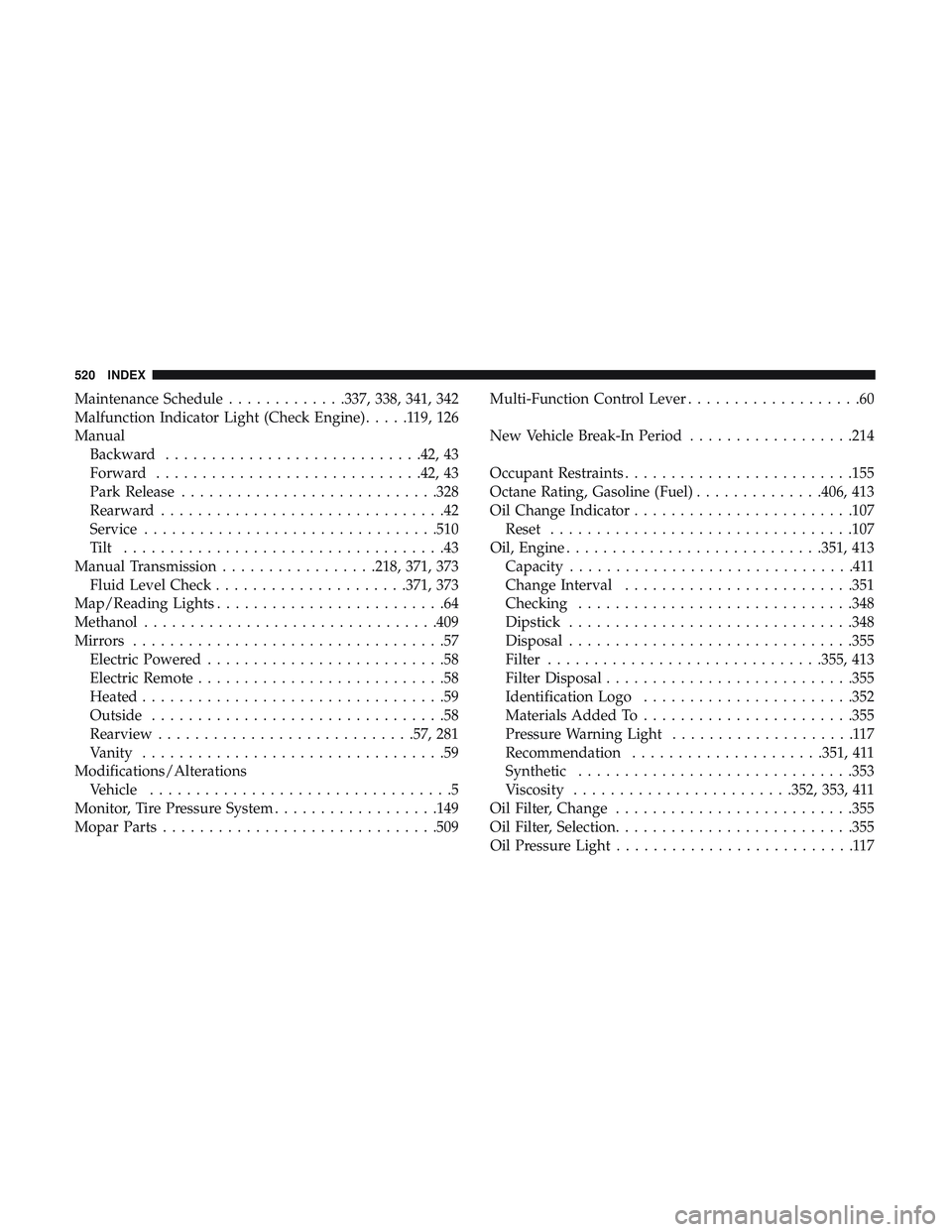
Maintenance Schedule.............337, 338, 341, 342
Malfunction Indicator Light (Check Engine) .....119,126
Manual Backward ........................... .42, 43
Forward ............................ .42, 43
Park Release ........................... .328
Rearward ...............................42
Service ............................... .510
Tilt ...................................43
Manual Transmission .................218, 371, 373
Fluid Level Check .....................371, 373
Map/Reading Lights .........................64
Methanol ............................... .409
Mirrors ..................................57
Electric Powered ..........................58
Electric Remote ...........................58
Heated .................................59
Outside ................................58
Rearview ........................... .57, 281
Vanity .................................59
Modifications/Alterations Vehicle .................................5
Monitor, Tire Pressure System ..................149
Mopar Parts ............................. .509Multi-Function Control Lever
...................60
New Vehicle Break-In Period ..................214
Occupant Restraints ........................ .155
Octane Rating, Gasoline (Fuel) ..............406, 413
Oil Change Indicator ....................... .107
Reset ................................ .107
Oil, Engine ........................... .351, 413
Capacity ...............................411
Change Interval ........................ .351
Checking ............................. .348
Dipstick .............................. .348
Disposal .............................. .355
Filter ............................. .355, 413
Filter Disposal .......................... .355
Identification Logo ...................... .352
Materials Added To ...................... .355
Pr
essure Warning Light ....................117
Recommendation .....................351, 411
Synthetic ............................. .353
Viscosity ....................... .352, 353, 411
Oil Filter, Change ......................... .355
Oil Filter, Selection ......................... .355
Oil Pressure Light ..........................117
520 INDEX