Page 153 of 232
151
Door pillar, right-hand side,
fuses
F Unclip the cover.
When you have finished, close the cover
very carefully.Fuses A (amps)
Allocation
54 -Not used
55 15Heated seats
56 15Rear passenger 12
V socket
57 10Under seat additional heating
58 15Heated rear screen, left-hand
59 15Heated rear screen, right-hand
60 -Not used
61 -Not used
62 -Not used
63 10Rear passenger additional heating control
64 -Not used
65 30Rear passenger additional heating fan
8
In the event of a breakdown
Page 154 of 232
152
Fuses in the engine
compartment
F Remove the nuts and tilt the box to access the fuses.
When you have finished, close the cover
very carefully. Fuses A (amps)
Allocation
1 40ABS pump feed
2 50Diesel pre-heating unit
3 30Ignition switch – Starter motor
4 40Fuel heater
5 20/50Cabin ventilation with additional programmable heating (battery +)
6 40/60Cabin fan maximum speed (battery +)
7 40/50/60 Cabin fan minimum speed (battery +)
8 40Cabin fan (ignition +)
9 15Rear 12
V socket (battery +)
10 15Horn
11 -Not used
14 15Front 12
V socket (battery +)
15 15Cigarette lighter (battery +)
16 -Not used
17 -Not used
18 7. 5Engine management control unit (battery +)
19 7. 5Air conditioning compressor
20 30Screenwash/headlamp wash pump
21 15Fuel pump supply
22 -Not used
23 30ABS solenoids
24 7. 5Auxiliary switch panel – Door mirror controls and folding (ignition +)
30 15Door mirror heating
In the event of a breakdown
Page 156 of 232

154
Starting using another
battery
Never try to start the engine by connecting
a battery charger.
Never use a
24 V or higher battery
b o o s t e r.
Check beforehand that the backup
battery has a
nominal voltage of 12 V and
a
capacity at least equal to that of the
discharged battery.
The two vehicles must not be in contact
with each other.
Switch off all the electrical consumers
on both vehicles (audio system, wipers,
lighting, etc.).
Make sure that the jump leads are not
close to moving parts of the engine (fan,
belts, etc.).
Do not disconnect the (+) terminal while
the engine is running.
After every reconnection of the battery, switch
on the ignition and wait 1
minute before
starting to allow the electronic systems to be
initialised. If slight difficulties are experienced
after this, please contact a
CITROËN dealer or
a
qualified workshop. The positive battery terminal A is accessible
via an access cover located at the side of the
fusebox.
Make connections only to the points indicated
and illustrated above. If you fail to follow this
instruction there is the danger of a
short-circuit!
F Connect the red cable to the battery terminal A then to the positive (+) terminal of
the backup battery B .
F
C
onnect one end of the green or black
cable to the negative (-) terminal of the
backup battery B .
F
C
onnect the other end of the green or black
cable to the earth point C on your vehicle.
F
O
perate the starter, let the engine run.
F
W
ait for the engine to return to idle, then
disconnect the cables.
A. Positive battery terminal on your vehicle B.
Backup battery
C. Earth on your vehicle
It is advisable to disconnect the negative
(-) terminal of the battery if the vehicle is
not to be used for a
period of more than
one month.
The description of the battery charging
procedure is given as an indication only.
If the battery has been disconnected for some
time, it may be necessary to reinitialise the
following functions:
-
t
he display parameters (date, time,
language, units of distance and
temperature),
-
r
adio stations,
-
c
entral locking.
Some settings are cleared and must be
reprogrammed; consult a
CITROËN dealer.
If your vehicle is fitted with a
tachograph or an
alarm, disconnection of the negative (-) terminal
of the battery (located under the floor on the
left-hand side, in the cab) is recommended
if the vehicle is not to be used for a
period of
more than 5
days.
In the event of a breakdown
Page 186 of 232

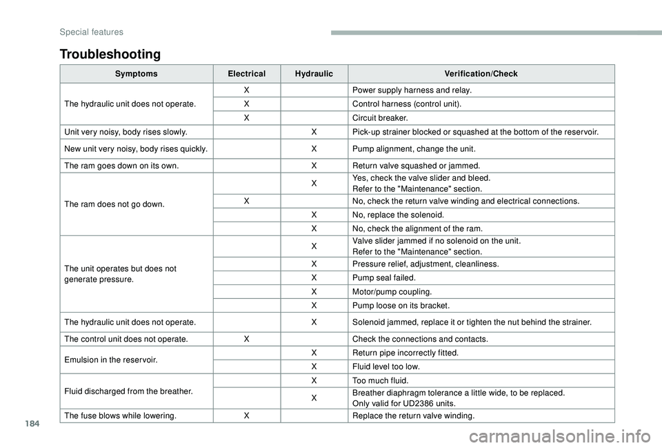
184
Troubleshooting
SymptomsElectricalHydraulic Verification/Check
The hydraulic unit does not operate. X
Power supply harness and relay.
X Control harness (control unit).
X Circuit breaker.
Unit very noisy, body rises slowly. X Pick-up strainer blocked or squashed at the bottom of the reser voir.
New unit very noisy, body rises quickly. X Pump alignment, change the unit.
The ram goes down on its own. X Return valve squashed or jammed.
The ram does not go down. X
Yes, check the valve slider and bleed.
Refer to the "Maintenance" section.
X No, check the return valve winding and electrical connections.
X No, replace the solenoid.
X No, check the alignment of the ram.
The unit operates but does not
generate pressure. X
Valve slider jammed if no solenoid on the unit.
Refer to the "Maintenance" section.
X Pressure relief, adjustment, cleanliness.
X Pump seal failed.
X Motor/pump coupling.
X Pump loose on its bracket.
The hydraulic unit does not operate. X Solenoid jammed, replace it or tighten the nut behind the strainer.
The control unit does not operate. XCheck the connections and contacts.
Emulsion in the reser voir. X
Return pipe incorrectly fitted.
X Fluid level too low.
Fluid discharged from the breather. X Too much fluid.
X
Breather diaphragm tolerance a
little wide, to be replaced.
Only valid for UD2386
units.
The fuse blows while lowering. XReplace the return valve winding.
Special features