2019 AUDI TT ROADSTER heating
[x] Cancel search: heatingPage 9 of 304

8S8012721BA
Quick access
OOOO
©
OOOOGOOOO
©
O
®OOO®
Side assist display ..............
Door handle
Central locking switch ...........
Air vent with seat heating controls
Lever for:
—Turn signals and high beams ....
— Active lane assist .............
Multifunction steering wheel with:
— Horn Pe
— Driver's airbag ...............
— Buttons for the virtual instrument
cluster, including the driver infor-
mation system, audio/video, tele-
phone, navigation and voice rec-
ognition system
—Shift paddles ................
Audi virtual cockpit (instrument
cluster) 22... 0... eee eee eee
Windshield washer system lever . .
Starting the engine if there is a
malfunction ..............00 00
Adjustable steering column ......
Cruise control lever .............
Instrument illumination .........
Hood release! » « wae ¢ s eae vs setee
Headlight control switch ........
Power exterior mirror adjustment .
Power windows ............005-
Air vent including climate control
system controls ................
Lockable glove compartment
Drives for CD, DVD, SIM/SD cards .
Front passenger's airbag ........
Rear window defogger button
Depending on equipment, buttons
for:
sdriverselect oc. seins 6 + cgies oo neve
— Electronic Stabilization Control
(ESC) «5 « cows ss owen 4 ¢ ee a8 i vee
—Emergency flashers ...........
— Retractable rear spoiler ........
Depending on equipment, center
console with:
— Multimedia compartment for cell
PNONG aces cs ees s Ree se BER es
75 25
39
72
193
66
10
42
59 57 70
Al
227
38
Al
28
52
153,
193
TT
86
40
90
159
= Audi phone box sessie ss owe oo cee 113
@) Infotainment system on/off button . 92
@5) Infotainment system unit ....... 92
@8 Wind deflector button .......... 35
@) Depending on equipment:
— Storage compartment
—Ashtray 0.2... 00. eee eee eee 48
—CUPHGIDES wis 5 2 wens s x eee 5 2: 49
Power top button .............. 33
@ Parking’ brake: « + cs ss wows so sors 59
G0 Depending on equipment:
—[START ENGINE STOP] button ... 57
— Sound button for exhaust door
control
@) Selector lever (S tronic).......... 62
@) Tips
Some the equipment listed here is only instal-
led in certain models or is available as an op-
tion.
Indicator lights overview
The indicator lights in the instrument cluster
blink or turn on. They indicate functions or mal-
functions.
With some indicator lights, messages may ap-
pear and warning signals may sound. The indica-
tor lights and messages may be covered by other
displays. To show them again, select the second
tab for messages with the multifunction steering
wheel © page 12.
Some indicator lights in the display can display in
several colors.
Some indicator lights turn on briefly as a function
check when you switch the ignition on. These sys-
tems are marked with a V in the following tables.
If one of these indicator lights does not turn on,
there is a malfunction in that system.
The following indicator lights may be available,
depending on the vehicle equipment:
Page 12 of 304

Instrument cluster
Instrument cluster
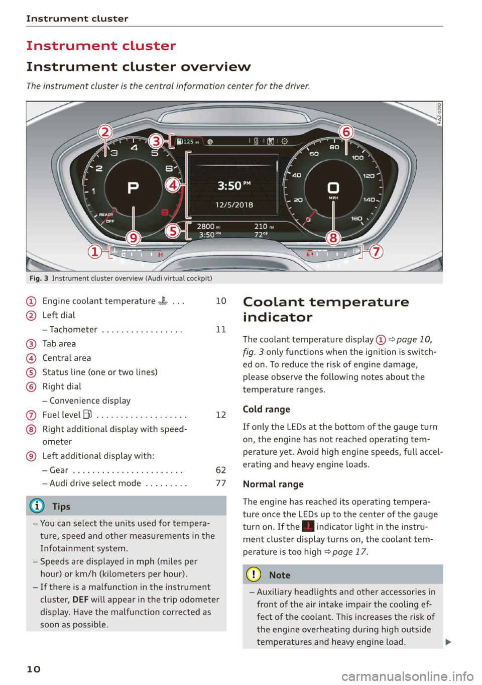
Instrument cluster overview
The instrument cluster is the central information center for the driver.
3:50™
12/5/2018
Fig. 3 Instrument cluster overview (Audi virtual cockpit)
Engine coolant temperature ~E ... 10
Left dial
—Tachometer ..........-...00- 11
Tab area
Central area
Status line (one or two lines)
Right dial
— Convenience display
Fuel level MD) .........0e eee e eee 12
Right additional display with speed-
ometer
Left additional display with:
SIGEAP sss sieves oo seme ow oaRe sw He 62
— Audi drive select mode ......... 77
@ Tips
— You can select the units used for tempera-
ture, speed and other measurements in the
Infotainment system.
— Speeds are displayed in mph (miles per
hour) or km/h (kilometers per hour).
— If there is a malfunction in the instrument
cluster, DEF will appear in the trip odometer
display. Have the malfunction corrected as
soon as possible.
©8
©OHO©
CO
©
10
Coolant temperature
indicator
The coolant temperature display @ > page 10,
fig. 3 only functions when the ignition is switch-
ed on. To reduce the risk of engine damage,
please observe the following notes about the
temperature ranges.
Cold range
If only the LEDs at the bottom of the gauge turn
on, the engine has not reached operating tem-
perature yet. Avoid high engine speeds, full accel-
erating and heavy engine loads.
Normal range
The engine has reached its operating tempera-
ture once the LEDs up to the center of the gauge
turn on. If the | indicator light in the instru-
ment cluster display turns on, the coolant tem-
perature is too high > page 17.
@) Note
— Auxiliary headlights and other accessories in
front of the air intake impair the cooling ef-
fect of the coolant. This increases the risk of
the engine overheating during high outside
temperatures and heavy engine load.
Page 13 of 304

8S8012721BA
Instrument cluster
— The front spoiler also helps to distribute
cooling air correctly while driving. If the
spoiler is damaged, the cooling effect will
be impaired and the risk of the engine over-
heating will increase. See an authorized Au-
di dealer or authorized Audi Service Facility
for assistance.
Tachometer
The tachometer (2) > page 10, fig. 3 displays the
engine speed in revolutions per minute (RPM).
The beginning of the red zone in the tachometer
indicates the maximum permissible engine speed
for all gears once the engine has been broken in.
Before reaching the red zone, you should shift in-
to the next higher gear, choose the "D" or "S" se-
lector lever position, or remove your foot from
the accelerator pedal.
Engine speed limitation
Applies to: vehicles with engine speed limitation
If the BB indicator light turns on, the engine will
be automatically limited to the RPM displayed in
the instrument cluster. This protects the engine
from overheating.
The engine speed limitation deactivates once the
engine is no Longer in the critical temperature
range and you have released the accelerator ped-
al once.
If the engine speed limitation was activated by
an engine control malfunction, the B indicator
light also turns on. Make sure the engine speed
does not go above the speed displayed, for exam-
ple when downshifting. Drive to an authorized
Audi dealer or authorized Audi Service Facility im-
mediately to have the malfunction corrected.
@) Note
The needle in the tachometer may only be in
the red area of the gauge for a short period of
time before there is a risk of damaging the
engine. The location where the red zone be-
gins varies depending on the engine.
Odometer
Fig. 4 Instrument cluster: odometer and reset button
The trip odometer and odometer are displayed in
the status line ©) > page 10, fig. 3.
The trip odometer shows the distance driven
since it was last reset. It can be used to measure
short distances. The odometer shows the total
distance that the vehicle has been driven.
Resetting the trip odometer
> Press the reset button [0-9] on the instrument
cluster. The trip odometer will be reset to zero.
@) Tips
Distances are displayed in mi (miles) or km
(kilometers).
Outside temperature
display
The outside temperature is displayed in the sta-
tus line ® page 10, fig. 3.
If your vehicle is stationary or if you are driving at
very low speeds, the temperature displayed in
the instrument cluster may be slightly higher
than the actual temperature outside due to heat
radiating from the engine.
At temperatures below 41 °F (+5 °C), a snowflake
symbol appears in front of the temperature dis-
play > A.
ZA\ WARNING
Do not assume the roads are free of ice based
on the outside temperature display. Be aware
that there may be ice on roads even when the
11
Page 14 of 304

Instrument cluster
outside temperature is around 41 °F (+5 °C)
and that ice can increase the risk of accidents.
Fuel level
The display @ > page 10, fig. 3 only works when
the ignition is switched on. When the display has
reached the reserve mark, a red LED turns on and
the i indicator light turns on > page 19.
For
the tank capacity in your vehicle, refer to the
Technical Data > page 285.
@ Note
Never drive until the tank is completely emp-
ty. The irregular supply of fuel that results
from that can cause engine misfires. Uncom-
busted fuel will then enter the exhaust sys-
tem. This can cause overheating and damage
to the catalytic converter.
Multifunction steering
wheel
Fig. 5 Driver information system display
Fig. 6 Left side of multifunction steering wheel
Requirement: the ignition must be switched on.
12
The driver information system contains multiple
tabs @ that display various information @).
The following tabs may be available, depending
on vehicle equipment:
First tab Vehicle functions
Second tab | Driver messages (this is only dis-
played if at least one indicator
light/message is being displayed)
=>page 16
Third tab Radio > page 147
Media > page 152
Fourth tab | Telephone > page 110
Fifth tab Navigation > page 132
Map > page 140
Sixth tab Sound > page 171
Audi connect > page 125
Settings > page 171
@l|k2] button
Switching tabs: press the [<>] button repeatedly
until the desired tab is shown (for example, Ra-
dio).
@l[VIEW] button
Changing the view > page 13.
@®|s] button
Return to functions at higher levels.
© Band [c] control buttons
Open/close the selection menu or options menu
=> page 13.
@ Left thumbwheel
— Selecting a function in a menu/list: turn the
left thumbwheel to the desired function ina
menu or list (such as selecting a station, Lap
times*).
— Confirming a selection: press the left thumb-
wheel (for example, confirm the station).
— Zooming in or out on the map: when a map is
displayed, turn the left thumbwheel up/down
to zoom in/out on the map.
Page 52 of 304

Stowing and using
Luggage compartment
General information
All pieces of luggage or objects must be securely
fastened in the luggage compartment. Note the
following to maintain good vehicle handling:
> Distribute the load evenly in the luggage com-
partment.
> Stow heavy luggage as far forward in the lug-
gage compartment as possible.
» Use non-elastic cords attached to the tie-downs
to secure objects.
Z\ WARNING
— Loose objects can be thrown around the ve-
hicle interior during sudden driving or brak-
ing maneuvers, which increases the risk of
an accident. Always stow objects securely in
the luggage compartment and secure them
at the tie-downs. Use straps suitable for
heavy objects.
— If pieces of luggage or objects are secured
to the tie-downs with unsuitable or dam-
aged straps, this can increase the risk of in-
jury during braking maneuvers or accidents.
— When transporting heavy objects, the vehi-
cle characteristics will change due to the
shift in the center of gravity, which increases
the risk of an accident. You may need to
adapt your driving style and speed to the
current conditions.
— The cargo net is only strong enough to se-
cure light objects. Heavy objects are not ade-
quately secured. Attempting to secure heavy
objects increases the risk of injury.
— Never exceed the permitted axle and load
and vehicle weight > page 286.
— Never secure a child safety seat to the tie-
downs.
— Never leave your vehicle unattended, espe-
cially if the luggage compartment lid is
open. Children could enter the luggage com-
partment and close the luggage compart-
ment lid from the inside. This creates the
risk of fatal injury, since the children would
be locked in and may not be able to escape
by themselves.
sO
— Do not allow children to play in or on the ve-
hicle. Close and lock the luggage compart-
ment lid as well as all other doors when you
leave the vehicle.
— Never transport passengers in the luggage
compartment. Every passenger must be cor-
rectly secured with the safety belts in the
vehicle > page 182.
() Note
Make sure that the heating grid strips for the
rear window defogger are not damaged by
abrasive objects.
G) Tips
— The tire pressure must be adapted to the
load > page 250.
— You can purchase straps at specialty stores.
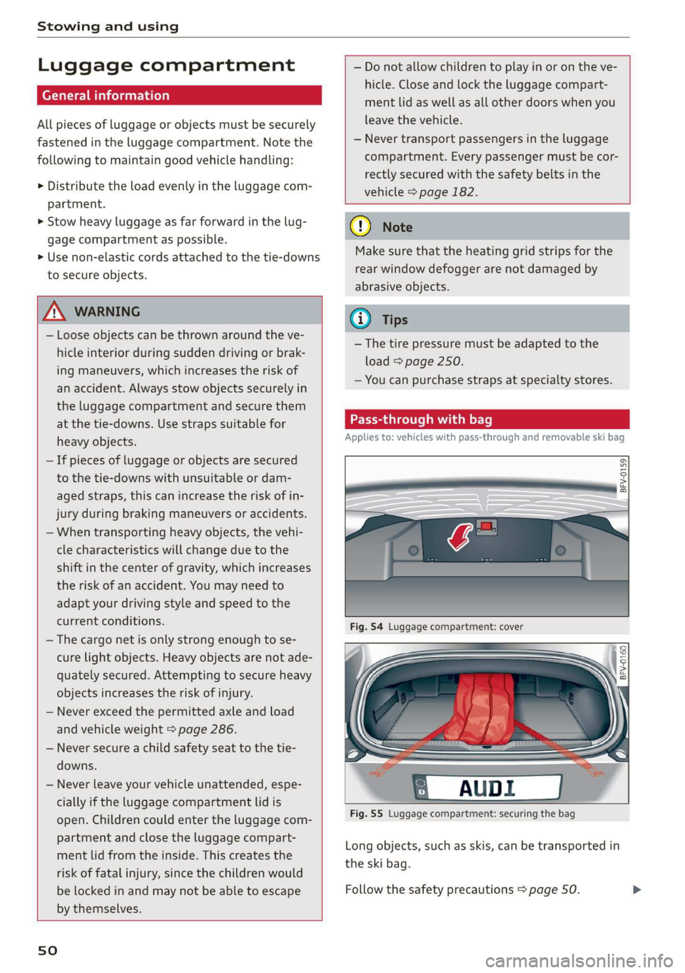
Pass-through with bag
Applies to: vehicles with pass-through and removable ski bag
BFV-0159
Fig. 55 Luggage compartment: securing the bag
Long objects, such as skis, can be transported in
the ski bag.
Follow the safety precautions > page 50.
Page 54 of 304

Warm and cold
Warm and cold
Climate control system
The climate control system warms, cools and re-
moves humidity from the air in the vehicle interi-
or. It functions most effectively when the win-
dows are closed. If there is a build-up of heat in-
side the vehicle, ventilation can help to speed up
the cooling process.
Pollutant filter
The pollutant filter removes pollutants such as
dust and pollen from the air.
Key recognition
Certain settings are automatically stored and as-
signed to the remote control key being used.
ZA WARNING
Poor visibility can lead to accidents.
— For safer driving, keep all windows free of
ice, snow and fog.
— Become familiar as quickly as possible with
the correct use and function of the climate
control system, especially with the defrost-
ing and defogging function.
— When the temperature is below freezing,
only use the windshield washer system after
the
windshield has been warmed by the cli-
mate control system. The washer fluid could
freeze on the windshield and impair visibili-
ty.
@) Note
— If you suspect that the climate control sys-
tem is damaged, switch the system off to
52
prevent further damage and have it checked
by an authorized Audi dealer or authorized
Audi Service Facility.
— Repairs to the Audi climate control system
require special technical knowledge and
special tools. Have it inspected by an au-
thorized Audi dealership or a qualified elec-
tronics store.
(@) For the sake of the environment
Reducing the amount of fuel used also re-
duces the amount of pollutants that enter the
alr.
G) Tips
—To prevent interference with the heating
and cooling output and to prevent the win-
dows from fogging over, the air intake in
front of the windshield must be free of ice,
snow, or leaves.
— Condensation from the cooling system can
drip and form a puddle of water under the
vehicle. This is normal and does not mean
there is a leak.
— The energy management system may tem-
porarily switch off certain functions, such as
the seat heating* or rear window defogger.
These systems are available again as soon as
the energy supply has been restored.
— The flows through the vents under the rear
window. Make sure the openings are not
covered when placing clothing on the lug-
gage compartment cover.
Page 55 of 304

8S58012721BA
Warm and cold
PNT erates elem icel eT)
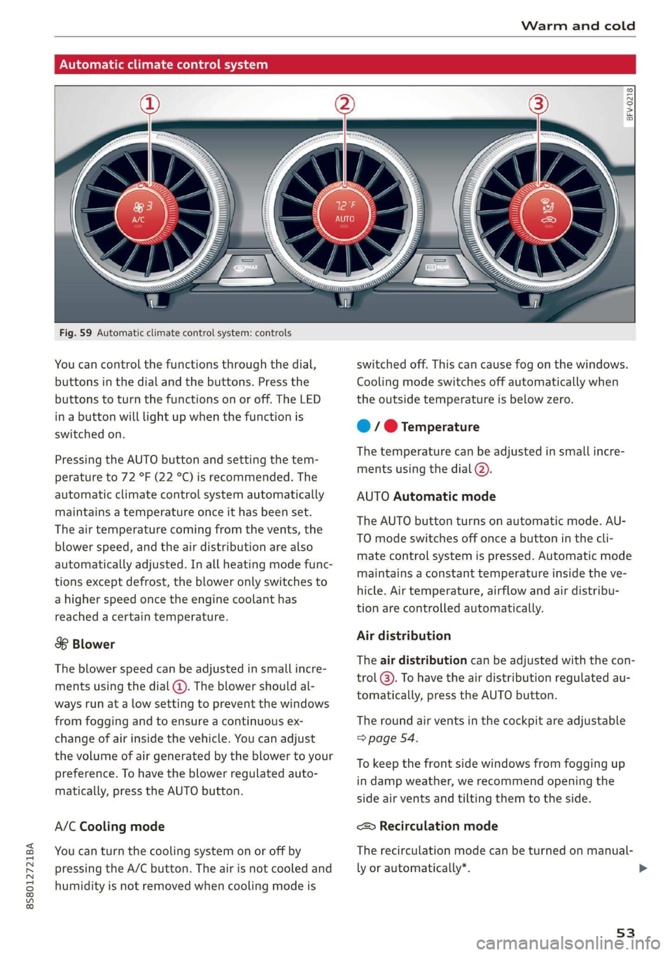
Fig. 59 Automatic climate control system: controls
You can control the functions through the dial,
buttons in the dial and the buttons. Press the
buttons to turn the functions on or off. The LED
in a button will light up when the function is
switched on.
Pressing the AUTO button and setting the tem-
perature to 72 °F (22 °C) is recommended. The
automatic climate control system automatically
maintains a temperature once it has been set.
The air temperature coming from the vents, the
blower speed, and the air distribution are also
automatically adjusted. In all heating mode func-
tions except defrost, the blower only switches to
a higher speed once the engine coolant has
reached a certain temperature.
8 Blower
The blower speed can be adjusted in small incre-
ments using the dial (@). The blower should al-
ways run at a low setting to prevent the windows
from fogging and to ensure a continuous ex-
change of air inside the vehicle. You can adjust
the volume of air generated by the blower to your
preference. To have the blower regulated auto-
matically, press the AUTO button.
A/C Cooling mode
You can turn the cooling system on or off by
pressing the A/C button. The air is not cooled and
humidity is not removed when cooling mode is
BFV-0218
switched off. This can cause fog on the windows.
Cooling mode switches off automatically when
the outside temperature is below zero.
@ / @ Temperature
The temperature can be adjusted in small incre-
ments using the dial (2).
AUTO Automatic mode
The AUTO button turns on automatic mode. AU-
TO mode switches off once a button in the cli-
mate control system is pressed. Automatic mode
maintains a constant temperature inside the ve-
hicle. Air temperature, airflow and air distribu-
tion are controlled automatically.
Air distribution
The air distribution can be adjusted with the con-
trol @). To have the air distribution regulated au-
tomatically, press the AUTO button.
The round air vents in the cockpit are adjustable
=> page 54.
To keep the front side windows from fogging up
in damp weather, we recommend opening the
side air vents and tilting them to the side.
<> Recirculation mode
The recirculation mode can be turned on manual-
ly or automatically*.
53
>
Page 56 of 304

Warm and cold
— Switching manual recirculation mode on and
off: Press the > button.
— Automatic* recirculation mode: auto recircula-
tion needs to be activated in the Infotainment
system. Select in the Infotainment system:
[MENU] button > Vehicle > left control button >
Vehicle settings > Air conditioning > Auto re-
circulation. The air quality sensor that is de-
signed for diesel and gasoline exhaust auto-
matically switches the recirculation mode on or
off depending on the level of pollutants in the
outside air.
In recirculation mode, the air inside the vehicle is
circulated and filtered. This prevents the unfil-
tered air outside the vehicle from entering the
vehicle interior. Switching recirculation mode on
when driving through a tunnel or when sitting in
traffic is recommended > A.
Pressing the <> button, AUTO or the & button
switches recirculation mode off.
® Defrosting
The windshield and side windows are defrosted
or cleared of condensation as quickly as possible.
The optimum amount of air flows mainly out of
the vents under the windshield. Recirculation
mode switches off. The temperature is controlled
automatically.
The AUTO button switches the defroster off.
{ Rear window defogger
If the rear window defogger is activated when
the ignition is switched on, the battery manage-
ment determines based on the battery charge if
it is possible to turn on. Otherwise, the rear win-
dow defogger functions with the engine running
and switches off automatically after approxi-
mately 10 - 20 minutes, depending on the out-
side temperature.
To prevent the rear window defogger from
switching off automatically, press and hold the
® button for more than two seconds. This re-
mains stored up to approximately 15 minutes af-
ter turning off the ignition.
54
Z\ WARNING
You should not use the recirculation mode for
an extended period since no fresh air is drawn
in. With the air-conditioning switched off, the
windows can fog up, which increases the risk
of an accident.
Adjusting the vents
BFV-0222
Fig. 60 Cockpit: adjusting the air vents
To adjust the direction of air flow, turn the
ridged outer adjustment wheel (@) fig. 60.
To adjust the amount of air flow, move the lever
@ on the air vent. To stop the air flow, move the
lever all the way to the left.
Syl)
Fig. 61 Air vents: seat heating
The seat heating has three levels. The selected
heat level is indicated by the LED.
> To switch the seat heating on, press the «/ but-
ton once.
> To switch to a lower level, press the «/ button
again.
> To switch the seat heating off, press the a but-
ton repeatedly until the LED turns off.