2019 AUDI TT ROADSTER stop start
[x] Cancel search: stop startPage 137 of 304
8S8012721BA
Navigation
Transferring a destination from the
directory
Applies to: vehicles with navigation system
You can navigate directly to destinations in the
directory.
Options — Show contact details
Bayelsa)
PAN RTO a aL
Hawthorn Ave, Los Angeles, CA
® Wilshire Blvd, Beverly Hills, CA
34°03°12.7°°N, 118°14°43.2°°W
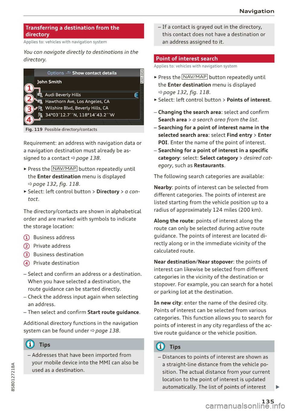
Fig. 119 Possible directory/contacts
Requirement: an address with navigation data or
a navigation destination must already be as-
signed to a contact > page 138.
> Press the LNAV/MAP] button repeatedly until
the Enter destination menu is displayed
=> page 132, fig. 118.
> Select: left control button > Directory > a con-
tact.
The directory/contacts are shown in alphabetical
order and are marked with symbols to indicate
the storage location:
@ Business address
@ Private address
@® Business destination
@ Private destination
— Select and confirm an address or a destination.
When you have selected a destination, the
route guidance can be started directly.
— Check the address input again when selecting
an address.
— Then select and confirm Start route guidance.
Additional directory functions in the navigation
system can be found under > page 138.
@ Tips
— Addresses that have been imported from
your mobile device into the MMI can also be
used as a destination.
— Ifa contact is grayed out in the directory,
this contact does not have a destination or
an address assigned to it.
meats)
Applies to: vehicles with navigation system
> Press the [NAV/MAP] button repeatedly until
the Enter destination menu is displayed
=> page 132, fig. 118.
> Select: left control button > Points of interest.
— Changing the search area: select and confirm
Search area > a search area from the list.
— Searching for a point of interest name in the
selected search area: select Find entry > Enter
POI. Enter the name of the point of interest.
— Searching for a point of interest in a specific
category: select: Select category > desired cat-
egory, such as Restaurants.
The following search categories are available:
Nearby: points of interest can be selected from
different categories. The points of interest are
listed starting from the vehicle position up toa
radius of approximately 124 miles (200 km).
Along the route: points of interest along the
route can only be selected during active route
guidance. The points of interest are located di-
rectly along or in the immediate vicinity of the
calculated route.
Near destination/Near stopover: the points of
interest can likewise be selected from different
categories in the vicinity of the destination or
stopover. For example, you can search for a hotel
or parking lot at the destination.
In new city: enter the name of the desired city.
Points of interest can be selected from various
categories. This function allows you to search for
points of interest in any city regardless of the ac-
tive route guidance or the vehicle position.
@) Tips
— Distances to points of interest are shown as
a straight-line distance from the vehicle po-
sition. The actual distance from your current
location to the point of interest is updated
automatically. The list of points of interest
135
>
Page 143 of 304
8S58012721BA
Navigation
— Switching the crosshairs on: press the control
knob in the map view.
— Switching the crosshairs off: press the [BACK
button.
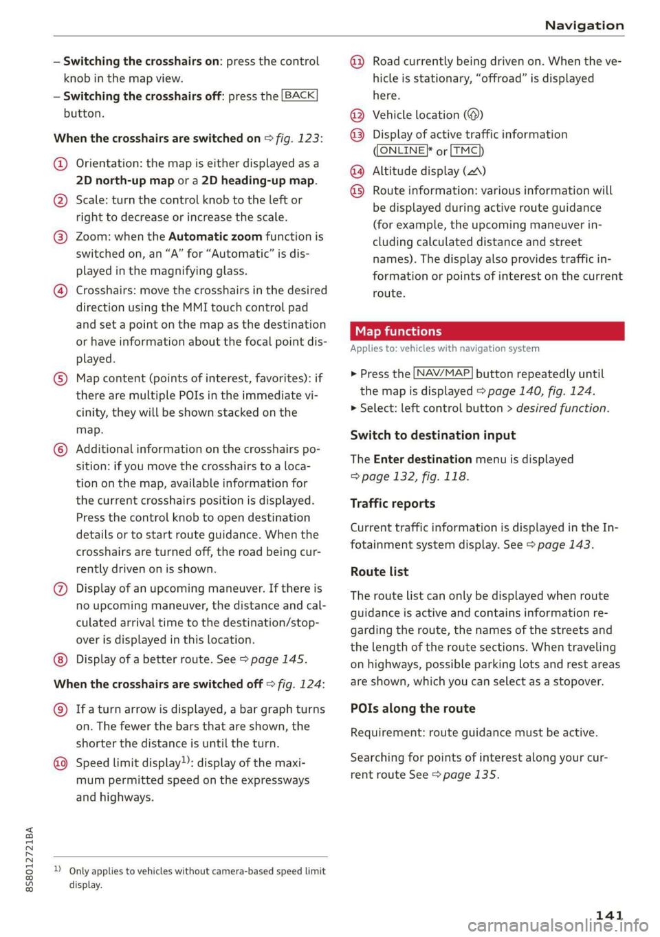
When the crosshairs are switched on > fig. 123:
@ Orientation: the map is either displayed as a
2D north-up map or a 2D heading-up map.
@) Scale: turn the control knob to the left or
right to decrease or increase the scale.
@ Zoom: when the Automatic zoom function is
switched on, an “A” for “Automatic” is dis-
played in the magnifying glass.
@ Crosshairs: move the crosshairs in the desired
direction using the MMI touch control pad
and set a point on the map as the destination
or have information about the focal point dis-
played.
© Map content (points of interest, favorites): if
there are multiple POIs in the immediate vi-
cinity, they will be shown stacked on the
map.
© Additional information on the crosshairs po-
sition: if you move the crosshairs to a loca-
tion on the map, available information for
the current crosshairs position is displayed.
Press the control knob to open destination
details or to start route guidance. When the
crosshairs are turned off, the road being cur-
rently driven on is shown.
@ Display of an upcoming maneuver. If there is
no upcoming maneuver, the distance and cal-
culated arrival time to the destination/stop-
over is displayed in this location.
Display of a better route. See > page 145.
When the crosshairs are switched off > fig. 124:
@) Ifa turn arrow is displayed, a bar graph turns
on. The fewer the bars that are shown, the
shorter the distance is until the turn.
Speed limit display): display of the maxi-
mum permitted speed on the expressways
and highways.
D_ Only applies to vehicles without camera-based speed limit
display.
@ Road currently being driven on. When the ve-
hicle is stationary, “offroad” is displayed
here.
Vehicle location (@)
Display of active traffic information
ONLINE} or [TMC
Altitude display (2)
Route information: various information will
be displayed during active route guidance
(for example, the upcoming maneuver in-
cluding calculated distance and street
names). The display also provides traffic in-
formation or points of interest on the current
route.
Applies to: vehicles with navigation system
®® O®
> Press the [NAV/MAP] button repeatedly until
the map is displayed > page 140, fig. 124.
> Select: left control button > desired function.
Switch to destination input
The Enter destination menu is displayed
=> page 132, fig. 118.
Traffic reports
Current traffic information is displayed in the In-
fotainment system display. See > page 143.
Route list
The route list can only be displayed when route
guidance is active and contains information re-
garding the route, the names of the streets and
the length of the route sections. When traveling
on highways, possible parking lots and rest areas
are shown, which you can select as a stopover.
POIs along the route
Requirement: route guidance must be active.
Searching for points of interest along your cur-
rent route See > page 135.
141
Page 157 of 304

8S8012721BA
Media
When importing, the audio files are automatical-
ly sorted into the media center categories based
on the stored additional information > page 161.
The copied video files are stored in the media
center under the Videos category.
Playing the Jukebox
Requirement: the Jukebox must contain audio/
video files > page 154, Adding files to the Juke-
box.
The Jukebox is accessed and operated through
the MMI @) & page 160, fig. 137.
Displaying Jukebox memory capacity
Select: right control button > Jukebox memory
capacity. Information about the Jukebox memory
capacity and the number of stored tracks is dis-
played.
Deleting tracks from the Jukebox!)
Requirement: the Jukebox must contain audio/
video files.
— Deleting an entry: select an entry from the
Jukebox media center. Select: right control but-
ton > Delete from jukebox > This entry or En-
tire list.
— The status of the deleting process is shown in
the MMI. Jukebox playback stops during the de-
leting process and starts again automatically
once the deletion is complete.
©) Note
Do not import audio/video files when the en-
gine is turned off because this will drain the
vehicle battery.
G) Tips
— Tracks from audio CDs cannot be imported
to the Jukebox for legal reasons.
— Files that have already been imported are
automatically recognized and cannot be
copied to the Jukebox again.
— It is not possible to play audio/video* files
in the CD/DVD* drive while importing them.
)) Not in the Playback view.
— The Jukebox does not provide an export
function due to legal reasons.
— Files or tracks without additional stored in-
formation are listed as Unknown. Audi rec-
ommends adding additional information
(such as ID3 tags) to audio files.
— Reset the Jukebox to the factory default set-
tings when selling your vehicle > page 172.
Bluetooth audio player
Applies to: vehicles with Bluetooth audio player
With the Bluetooth audio player, you can play
music wirelessly from your Bluetooth-capable
device (such as a cell phone) through the MMI.
Requirement: the vehicle must be stationary and
the ignition must be switched on. The Bluetooth
settings will open on your mobile device during
the connection setup. The Bluetooth function and
visibility of the MMI > page 174 and mobile de-
vice must be switched on. The Bluetooth audio
player > page 174 must be switched on in the
MMI.
— Connecting a Bluetooth device: press the
MEDIA] button. Press the left control button
until the sources overview is displayed. Select
and confirm Bluetooth audio player ©)
=> page 160, fig. 138.
—If necessary, select and confirm, Not connected
> Connect Bluetooth audio player. The Blue-
tooth device search starts. Follow the instruc-
tions in the MMI.
— Select and confirm the desired Bluetooth device
from the list. The MMI generates a PIN for the
connection.
— Select and confirm Yes.
— Enter the PIN for connecting on your Bluetooth
device. Or: if the PIN is already displayed on
your Bluetooth device, confirm it in the Blue-
tooth device and in the MMI. The time allowed
for entering the PIN is limited to approximately
30 seconds.
The media is started and operated through the
mobile device or the MMI, depending on the de-
vice being used.
155
>
Page 177 of 304
8S8012721BA
System settings
Start update. The length of the process de-
pends on the size of the update.
— Reset driver installation: the selected media
driver package is reset to the settings at the
time of delivery.
— Version information: information on the MMI
software version and the navigation database*
software version is displayed. The Software in-
formation function also provides information
on the software contained in the MMI and the
licensing agreement.
Sound settings
The sound distribution and volume of the MMI
can be adjusted individually. The settings depend
on the vehicle equipment.
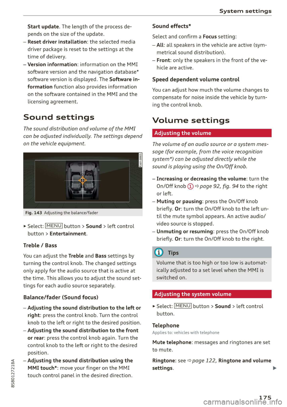
Fig. 143 Adjusting the balance/fader
> Select: [MENU] button > Sound > left control
button > Entertainment.
Treble / Bass
You can adjust the Treble and Bass settings by
turning the control knob. The changed settings
only apply for the audio source that is active at
the time. This allows you to adjust the sound set-
tings for each audio source separately.
Balance/fader (Sound focus)
— Adjusting the sound distribution to the left or
right: press the control knob. Turn the control
knob to the left or right to the desired position.
— Adjusting the sound distribution to the front
or rear: press the control knob again. Turn the
control knob to the left or right to the desired
position.
— Adjusting the sound distribution using the
MMI touch*: move your finger on the MMI
touch control panel in the desired direction.
Sound effects*
Select and confirm a Focus setting:
— All: all speakers in the vehicle are active (sym-
metrical sound distribution).
— Front: only the speakers in the front of the ve-
hicle are active.
Speed dependent volume control
You can adjust how much the volume changes to
compensate for noise inside the vehicle by turn-
ing the control knob.
Volume settings
Adjusting the volume
The volume of an audio source or a system mes-
sage (for example, from the voice recognition
system*) can be adjusted directly while the
sound is playing using the On/Off knob.
— Increasing or decreasing the volume: turn the
On/Off knob @) 9 page 92, fig. 94 to the right
or left.
—Muting or pausing: press the On/Off knob
briefly. Or: turn the On/Off knob to the left un-
til the mute symbol appears. An active audio/
video source is stopped.
—Unmuting or resuming: press the On/Off knob
briefly. Or: turn the On/Off knob to the right.
G@) Tips
Volume that is too high or too low is automat-
ically adjusted to a set level when the MMI is
switched on.
Adjusting the system volume
> Select: [MENU] button > Sound > left control
button.
Telephone
Applies to: vehicles with telephone
Mute telephone: messages and ringtones are set
to mute.
Ringtone: see => page 122, Ringtone and volume
settings.
175
Page 228 of 304
Checking and Filling
diesel misfueling guard. If this is the case,
try turning the nozzle before inserting it in
the fuel filler neck, use a different fuel
pump, or see an authorized Audi dealer or
authorized Audi Service Facility for assis-
tance.
— The misfueling guard does not open when
adding fuel from a fuel container. When re-
fueling with a reserve canister, you must use
the
funnel stored in the luggage compart-
ment > page 226, fig. 168.
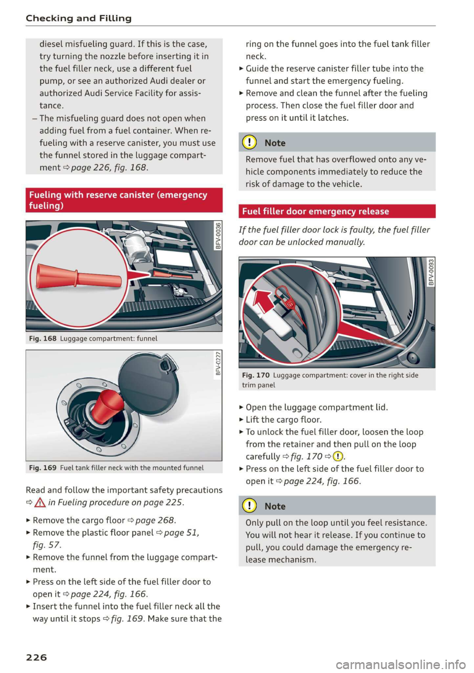
Fueling with reserve canister (emergency
fueling)
° i) 3°
8 >
c co
BFV-0227
Fig. 169 Fuel tank filler neck with the mounted funnel
Read and follow the important safety precautions
= A\ in Fueling procedure on page 225.
> Remove the cargo floor > page 268.
> Remove the plastic floor panel > page 51,
fig. 57.
> Remove the funnel from the luggage compart-
ment.
> Press on the left side of the fuel filler door to
open it > page 224, fig. 166.
> Insert the funnel into the fuel filler neck all the
way until it stops > fig. 169. Make sure that the
226
ring on the funnel goes into the fuel tank filler
neck.
> Guide the reserve canister filler tube into the
funnel and start the emergency fueling.
>» Remove and clean the funnel after the fueling
process. Then close the fuel filler door and
press on it until it latches.
() Note
Remove fuel that has overflowed onto any ve-
hicle components immediately to reduce the
risk of damage to the vehicle.
Fuel filler door emergency release
If the fuel filler door lock is faulty, the fuel filler
door can be unlocked manually.
| a 3
= >
cg a
Fig. 170 Luggage compartment: cover in the right side
trim panel
> Open the luggage compartment lid.
> Lift the cargo floor.
> To unlock the fuel filler door, loosen the loop
from the retainer and then pull on the loop
carefully > fig. 170 >@.
> Press on the left side of the fuel filler door to
open it > page 224, fig. 166.
@) Note
Only pull on the loop until you feel resistance.
You will not hear it release. If you continue to
pull, you could damage the emergency re-
lease mechanism.
Page 229 of 304

8S58012721BA
Checking and Filling
Emissions control
system
General information
ZA WARNING
The temperature of the exhaust system is
high, both when driving and after stopping
the engine.
— Never touch the exhaust tail pipes once they
have
become hot. This could result in burns.
— Do not park your vehicle over flammable
materials such as grass or leaves because
the high temperature of the emissions sys-
tem could start a fire.
— Do not apply underbody protectant in the
exhaust system area, because this increases
the risk of fire.
(e)e-1 Mid (Reel Tale
Follow the safety precautions > page 227, Gener-
al information.
The vehicle may only be driven with unleaded
gasoline, or the catalytic converter will be de-
stroyed.
Never drive until the tank is completely empty.
The irregular supply of fuel that results from that
can cause engine misfires. Uncombusted fuel
could enter the exhaust system, which could
cause overheating and damage to the catalytic
converter.
On Board Diagnostic System (OBD)
The On Board Diagnostic System monitors the
engine and transmission components that influ-
ence emissions.
- 5
z é
port for the On Board Diagnostic System (OBD)
On Board Diagnostic System
Engine data can be read out at the On Board Di-
agnostic System connection port using a special
testing device > fig. 171.
Indicator light
If the S indicator light blinks or turns on, there
is a malfunction that is causing poor emissions
quality and that could damage the catalytic con-
verter. Drive slowly to an authorized Audi dealer
or authorized Audi Service Facility to have the
malfunction corrected.
Z\ WARNING
Incorrect use of the connection port for the
On Board Diagnostic System can cause mal-
functions, which can then result in accidents
and serious injuries.
— Only allow an authorized Audi dealer or au-
thorized Audi Service Facility to read out the
engine data.
Engine compartment
General information
Special care is required if you are working in the
engine compartment
For work in the engine compartment, such as
checking and filling fluids, there is a risk of in-
jury, scalding, accidents, and burns. For this
227
>
Page 259 of 304

8S8012721BA
Wheels
overheat and can lead to tire failure. Under-infla-
tion also reduces fuel efficiency and tire tread
life, and may affect the vehicle's handling and
stopping ability.
Please note that the TPMS is not a substitute for
proper tire maintenance, and it is the driver's re-
sponsibility to maintain correct tire pressure,
even if under-inflation has not reached the level
to trigger illumination of the TPMS low tire pres-
sure telltale.
Your vehicle has also been equipped with a TPMS
malfunction indicator to indicate when the sys-
tem is not operating properly. The TPMS mal-
function indicator is combined with the low tire
pressure telltale. When the system detects a
malfunction, the telltale will flash for approxi-
mately one minute and then remain continuously
illuminated. This sequence will continue upon
subsequent vehicle start-ups as long as the mal-
function exists.
When the malfunction indicator is illuminated,
the system may not be able to detect or signal
low tire pressure as intended. TPMS malfunctions
may occur for a variety of reasons, including the
installation of replacement or alternate tires or
wheels on the vehicle that prevent the TPMS
from functioning properly. Always check the
TPMS malfunction telltale after replacing one or
more tires or wheels on your vehicle to ensure
that the replacement or alternate tires and
wheels allow the TPMS to continue to function
properly.
If the Tire Pressure Monitoring System
indicator appears
Applies to: vehicles with Tire Pressure Monitoring System in-
dicator
The tire pressure indicator in the instrument
cluster informs you if the tire pressure is too low
or if there is a system malfunction.
Using the ABS sensors, the tire pressure monitor-
ing system compares the tire tread circumference
and vibration characteristics of the individual
tires. If the pressure changes in one or more
tires, this is indicated in the Infotainment system
display with an indicator light @ and a message.
If only one tire is affected, the location of that
tire will be indicated.
The tire pressures must be stored in the Infotain-
ment system again each time the pressures
change (switching between partial and full load
pressure) or after changing or replacing a tire on
your vehicle > page 258. The tire pressure moni-
toring system only monitors the tire pressure you
have stored. Refer to the tire pressure label for
the recommended tire pressure for your vehicle
=> page 250, fig. 184.
Tire tread circumference and vibration character-
istics can change and cause a tire pressure warn-
ing if:
— The tire pressure in one or more tires is too low
— The tire has structural damage
— The tire was replaced or the tire pressure was
changed and it was not stored > page 258
— The spare tire* is installed
Indicator lights
@® - Loss of pressure in at least one tire > A\.
Check the tires and replace or repair if necessary.
Check/correct the pressures of all four tires and
store the pressure again in the Infotainment sys-
tem > page 258.
ia (Tire Pressure Monitoring System) Tire pres-
sure: malfunction! See owner's manual - if io
appears after switching on the ignition or while
driving and then the @) indicator light in the in-
strument cluster also starts to blink for about
one minute and then stays on permanently, there
is a system malfunction. Try to store the correct
tire pressures > page 258. If the indicator light
does turn off or turns on again after a short peri-
od of time, drive to an authorized Audi dealer or
authorized Audi Service Facility immediately to
have the malfunction corrected.
ZA WARNING
— If the tire pressure indicator appears in the
display, reduce your speed immediately and
avoid any hard steering or braking maneu-
vers. Stop as soon as possible and check the
tires and their pressure.
257
Page 260 of 304
Wheels
— The driver is responsible for maintaining the
correct tire pressures. You must check the
tire pressures regularly.
— Under certain conditions (such as a sporty
driving style, winter conditions or unpaved
roads), the pressure monitor indicator may
be delayed.
— Do not use run-flat tires on your vehicle. Us-
ing them when not permitted can lead to ve-
hicle damage or accidents.
G) Tips
— The tire pressure monitoring system can al-
so stop working when there is an ESC mal-
function.
— Using snow chains may result in a system
malfunction.
— The tires with the identification “AO”
= page 247 have been matched with your
Audi tire pressure monitoring system. Using
these tires is recommended.
Storing tire pressures
Applies to: vehicles with Tire Pressure Monitoring System in-
dicator
If the tire pressure changes or a tire is replaced,
it must be confirmed in the Infotainment sys-
tem.
> Before storing the tire pressures, make sure the
tire pressures in all four tires meet the speci-
fied values and are adapted to the load
=> page 248.
> Switch the ignition on.
> Select in the Infotainment system: the
button > Vehicle > left control button > Service
& checks > Tire pressure monitoring.
G) Tips
Do not store the tire pressures if snow chains
are installed.
MENU
258
Tire pressure monitoring
system
(1) General notes
Each tire, including the spare (if provided),
should be checked monthly when cold and inflat-
ed to the inflation pressure recommended by the
vehicle manufacturer on the vehicle placard or
tire inflation pressure label. (If your vehicle has
tires of a different size than the size indicated on
the vehicle placard or tire inflation pressure la-
bel, you should determine the proper tire infla-
tion pressure for those tires).
As an added safety feature, your vehicle has been
equipped with a tire pressure monitoring system
(TPMS) that illuminates a low tire pressure tell-
tale when one or more of your tires is significant-
ly under-inflated. Accordingly, when the low tire
pressure telltale illuminates, you should stop and
check your tires as soon as possible, and inflate
them to the proper pressure. Driving on a signifi-
cantly under-inflated tire causes the tire to over-
heat and can lead to tire failure. Under-inflation
also reduces fuel efficiency and tire tread life,
and may affect the vehicle's handling and stop-
ping ability.
Please note that the TPMS is not a substitute for
proper tire maintenance, and it is the driver's re-
sponsibility to maintain correct tire pressure,
even if under-inflation has not reached the level
to trigger illumination of the TPMS low tire pres-
sure telltale.
Your vehicle has also been equipped with a TPMS
malfunction indicator to indicate when the sys-
tem is not operating properly. The TPMS mal-
function indicator is combined with the low tire
pressure telltale. When the system detects a
malfunction, the telltale will flash for approxi-
mately one minute and then remain continuously
illuminated. This sequence will continue upon
subsequent vehicle start-ups as long as the mal-
function exists.
When the malfunction indicator is illuminated,
the system may not be able to detect or signal
low
tire pressure as intended. TPMS malfunctions
may occur for a variety of reasons, including the >