Page 26 of 292
2. Push the unlock button on the key fob or the doorlocking/unlocking LED indicator button on the
dashboard.
3. Push the lock button on the key fob or the door locking/unlocking LED indicator button on the
dashboard.
Emergency Door Locking Device
Passenger Side Door
The passenger side door has a device to lock it when the
vehicle’s battery is discharged.
To lock it, place the metal insert of the ignition key into
the emergency lock and turn it clockwise. To restore the starting condition of the door locks (only
if battery charge is restored), proceed as follows:
•
Push the unlock button on the key fob.
• Push the door locking/unlocking LED indicator but-
ton on the dashboard.
• Introduce the metal insert of the ignition key in the
front door pawl.
• Pull the internal door handle.
Emergency Door Locking Device
24 GETTING TO KNOW YOUR VEHICLE
Page 34 of 292

Follow Me Home/Headlight Delay
When this feature is selected, the driver can choose to
have the headlights remain on for a preset period of
time after the engine is turned OFF.
Activation
Remove the key or turn the ignition to the STOP
(OFF/LOCK) position, and pull the multifunction lever
toward the steering wheel within two minutes. Each
time the lever is pulled, the activation of the lights will
be extended by 30 seconds. The activation of the lights
can be extended to a maximum of 210 seconds.
Deactivation
Pull the multifunction lever toward the steering wheel
and hold it for more than two seconds.
Turn Signals
Move the multifunction lever up or down and the
arrows on each side of the instrument cluster flash to
show proper operation of the front and rear turn signal
lights.NOTE:
If either light remains on and does not flash, or
there is a very fast flash rate, check for a defective
outside light bulb. If an indicator fails to light when the
lever is moved, it would suggest that the indicator bulb
is defective.
Lane Change Assist
Tap the lever up or down once, without moving beyond
the detent, and the turn signal (right or left) will flash
five times then automatically turn off.
INTERIOR LIGHTS
Interior Light
The interior light is located in the headliner in between
the sun visors. The interior light can be set to three
different positions (off/left position, center position,
on/right position).
Using the interior light lens, push the lens to the right
from its center position and the lights are always on.
Push the lens to the left from its center position and the
lights are always off. Leave the lens in the center
position, and the light is turned on and off when the
doors are opened or closed.
32 GETTING TO KNOW YOUR VEHICLE
Page 35 of 292
CAUTION!
Before getting out of the vehicle be sure that the
Overhead Dome Lamp is in the center position or
that the lights are off to avoid draining the battery.
Interior Light Timing (Center Position)
There are four different modes of operation that can be
activated in this position:
•When one door is opened, a three minute timer is
activated. •
When the key is removed from the ignition (within
two minutes of the ignition being turned OFF), a 10
second timer is activated.
• When the doors are unlocked with the key fob, a 10
second timer is activated.
• When the doors are locked with the key fob, the
lights will turn off.
Dimmer Controls
The dimmer controls are located on the left side of the
instrument panel below the instrument cluster.
Interior Light (Off Position Shown)
Dimmer Controls
3
GETTING TO KNOW YOUR VEHICLE 33
Page 43 of 292

3. Turn the Blower Control counterclockwise to reducethe fan speed.
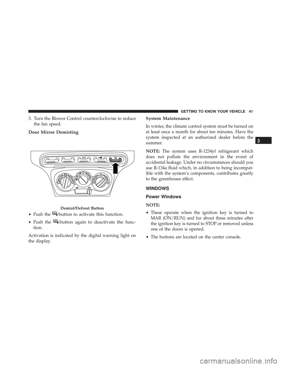
Door Mirror Demisting
•Push thebutton to activate this function.
•Push thebutton again to deactivate the func-
tion.
Activation is indicated by the digital warning light on
the display.
System Maintenance
In winter, the climate control system must be turned on
at least once a month for about ten minutes. Have the
system inspected at an authorized dealer before the
summer.
NOTE: The system uses R-1234yf refrigerant which
does not pollute the environment in the event of
accidental leakage. Under no circumstances should you
use R-134a fluid which, in addition to being incompat-
ible with the system’s components, contributes greatly
to the greenhouse effect.
WINDOWS
Power Windows
NOTE:
• These operate when the ignition key is turned to
MAR (ON/RUN) and for about three minutes after
the ignition key is turned to STOP or removed unless
one of the doors is opened.
• The buttons are located on the center console.Demist/Defrost Button
3
GETTING TO KNOW YOUR VEHICLE 41
Page 46 of 292
2. From the passenger side with the door open, movethe two side locking handles towards each other and
lift the top from the retainers.
3. Roll up the soft top to the center of the vehicle, repeat the procedure on the driver’s side of the vehicle. 4. Remove the soft top with both sides rolled up.
5. Place the pin buffer over the front locking handle
pins to prevent damage to the soft top during
storage.
Side Locking Handles
Soft Top Removal
44 GETTING TO KNOW YOUR VEHICLE
Page 64 of 292

•The fuel pump symbol points to the side of
the vehicle where the fuel door is located.
5. “Alfa DNA” Driving Mode Indicator
•This area of the cluster displays which driving
mode the vehicle is currently in. A letter (d, n, or a)
corresponding to the active driving mode (dynamic
or race, natural, all weather) and a dedicated mes-
sage is shown on the display.
NOTE: The hard telltales will illuminate for a bulb
check when the ignition is first cycled.
INSTRUMENT CLUSTER DISPLAY
Your vehicle is equipped with an instrument cluster
display, which offers useful information to the driver.
With the ignition in the STOP (OFF/LOCK) position
(and the key removed, for vehicles with mechanical
key), opening/closing of a door will activate the display
for viewing, and display the total miles or kilometers in
the odometer. Your instrument cluster display is de-
signed to display important information about your
vehicle’s systems and features. Using a driver interac-
tive display located on the instrument panel, your
instrument cluster display can show you how systems
are working and give you warnings when they aren’t. The steering wheel mounted controls allow you to scroll
through and enter the main menus and submenus. You
can access the specific information you want and make
selections and adjustments.
Location And Controls
The instrument cluster display features a driver-
interactive display that is located in the instrument
cluster.
The instrument cluster display consists of the following:
•
Digital Speedometer
Instrument Cluster Display
62 GETTING TO KNOW YOUR INSTRUMENT PANEL
Page 70 of 292

4. Push and release theupordown arrow button for
setting.
5. Briefly push the SET/BACKbutton and “day” will
flash on the display.
6. Push and release the upordown button for setting.
NOTE: The setting will increase or decrease by one
unit each time the upordown arrow button is pushed.
Push and hold the upordown arrow button to
increase/decrease the setting rapidly. Save the setting
by briefly pushing the button when you approach the
required setting.
Briefly push the SET/BACKbutton to go back to the
menu screen, or push and hold the SET/BACKbutton
(approximately one second) to go back to the main
screen without storing the settings.
Autoclose
With this function active, the doors will automatically lock
at when the vehicle’s speed exceeds 12 MPH (20 km/h).
To change the setting, proceed as follows:
1. Briefly push the SET/BACKbutton “On” or “Off”
will flash on the display (according to the previous
setting). 2. Push and release the
upordown arrow button for
setting.
3. Briefly push the SET/BACKbutton to go back to the
menu screen, or push and hold the SET/BACK
button (approximately one second) to go back to the
main screen without storing the settings.
Units (Set Units)
This function may be used to set the measurement unit
in three submenus: “Distance,” “Temperature” and
“Fuel Economy.”
To set the required unit, proceed as follows:
1. Briefly push the SET/BACKbutton to display the
three submenus.
2. Push and release the upordown arrow button to
navigate the three submenus.
3. Select the required submenu and then briefly push the SET/BACK button.
4. When accessing the “Distance” submenu, briefly push the SET/BACK button. Either “mi” or “km”
will appear on the display (according to the previous
setting).
68 GETTING TO KNOW YOUR INSTRUMENT PANEL
Page 116 of 292

WARNING!
Do not mount equipment, or stack luggage or other
cargo up high enough to block the deployment of
the SABICs. The door trim below the side windows
where the SABIC and its deployment path are
located should remain free from any obstructions.
Side Impacts
The Side Air Bags are designed to activate in certain
side impacts. The Occupant Restraint Controller (ORC) determines whether the deployment of the Side Air
Bags in a particular impact event is appropriate, based
on the severity and type of collision. The side impact
sensors aid the ORC in determining the appropriate
response to impact events. The system is calibrated to
deploy the Side Air Bags on the impact side of the
vehicle during impacts that require Side Air Bag occu-
pant protection. In side impacts, the Side Air Bags
deploy independently; a left side impact deploys the
left Side Air Bags only and a right-side impact deploys
the right Side Air Bags only. Vehicle damage by itself is
not a good indicator of whether or not Side Air Bags
should have deployed.
The Side Air Bags will not deploy in all side collisions,
including some collisions at certain angles, or some side
collisions that do not impact the area of the passenger
compartment. The Side Air Bags may deploy during
angled or offset frontal collisions where the front air
bags deploy.
Side Air Bags are a supplement to the seat belt restraint
system. Side Air Bags deploy in less time than it takes to
blink your eyes.
Supplemental Door-Integrated Side Air Bag Inflatable
Curtains (SABICs) Location
114 SAFETY