Page 37 of 90
Instrument and control functions
4-11
4
5. Wait a few seconds, and then in-
stall the bleed screws.
6. Install the protector.
EAU84211
A djustin g the shock a bsor ber
assem bly
This shock absorber assembly is
equipped with a spring preload adjust-
ing nut, a rebound damping force ad-
justing screw and a compression
damping force adjusting screw.
NOTICE
ECA10102
To avoi d d amag ing the mechanism,
d o not attempt to turn b eyond the
maximum or minimum settin gs.
Sprin g preloa d
Adjust the spring preload as follows. 1. Remove the seat. (See page 4-8.)
2. Loosen the clamp bolt.
3. Remove the bolts, and then take the panels off.
1. Bleed screw
1 1
1. Clamp bolt
1. Bolt
2. Panel
1
1
2
UBR880E0.book Page 11 Friday, February 16, 2018 8:32 AM
Page 38 of 90
Instrument and control functions
4-12
4 4. Remove the muffler bolt, and then
remove the muffler.
5. Remove the rear frame bolts, and then remove the rear frame as-
sembly. 6. Loosen the locknut.
7. To increase the spring preload
and thereby harden the suspen-
sion, turn the adjusting nut in di-
rection (a). To decrease the spring
preload and thereby soften the
suspension, turn the adjusting nut
in direction (b).
A special wrench can be ob-
tained at a Yamaha dealer to
make this adjustment.
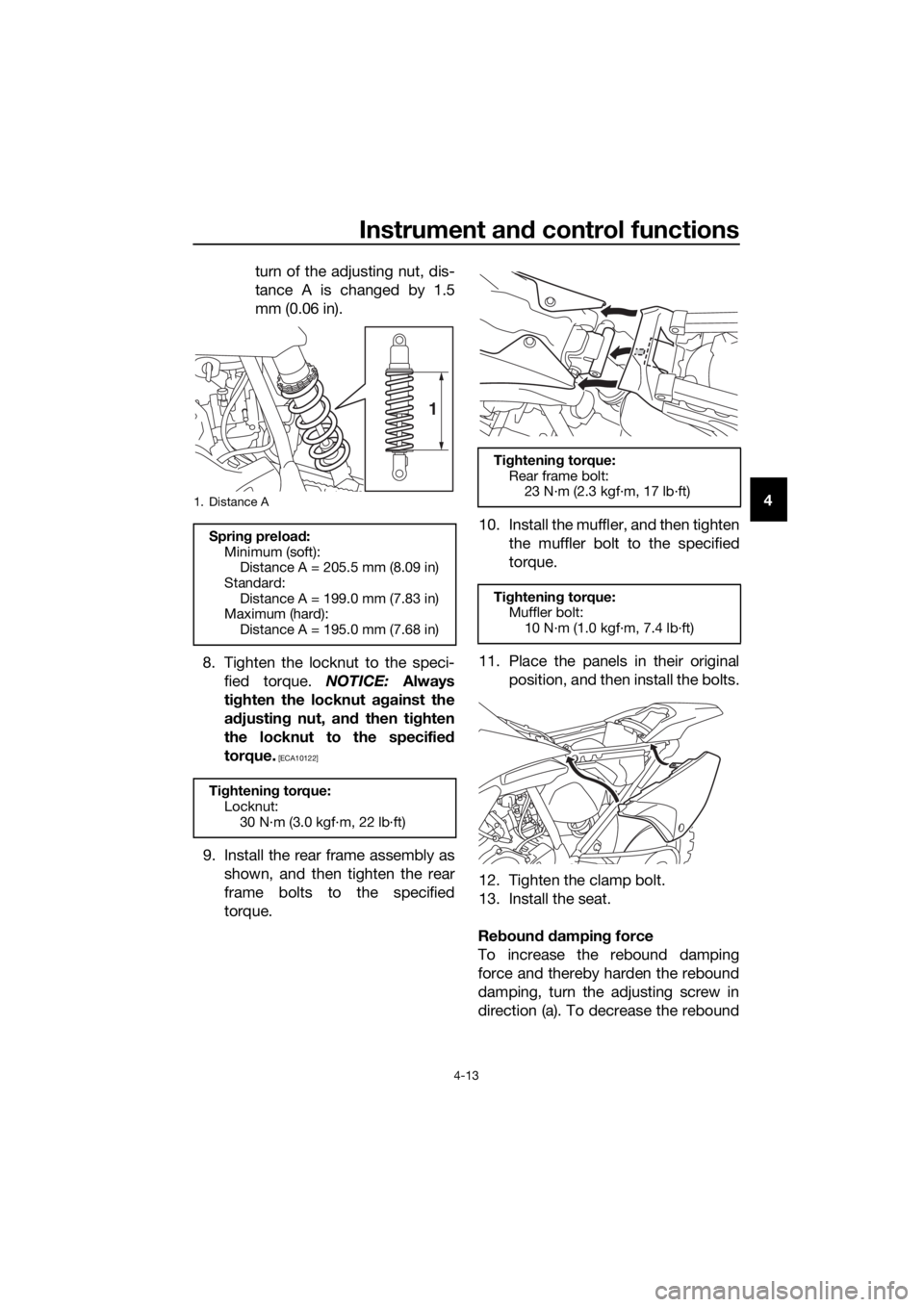
The spring preload setting is
determined by measuring
distance A, shown in the illus-
tration. The longer distance A
is, the lower the spring pre-
load; the shorter distance A
is, the higher the spring pre-
load. With each complete
1. Bolt
2. Panel
1. Muffler
2. Muffler bolt
1. Rear frame assembly
2. Rear frame bolt
1
2
2
1
2
1
1. Rear frame assembly
2. Rear frame bolt
1. Locknut
2. Spring preload adjusting nut
2
1
1
2
(a)
(b)
UBR880E0.book Page 12 Friday, February 16, 2018 8:32 AM
Page 39 of 90

Instrument and control functions
4-13
4
turn of the adjusting nut, dis-
tance A is changed by 1.5
mm (0.06 in).
8. Tighten the locknut to the speci- fied torque. NOTICE: Always
ti g hten the locknut ag ainst the
a d justin g nut, an d then ti ghten
the locknut to the specified
torque.
[ECA10122]
9. Install the rear frame assembly as shown, and then tighten the rear
frame bolts to the specified
torque. 10. Install the muffler, and then tighten
the muffler bolt to the specified
torque.
11. Place the panels in their original position, and then install the bolts.
12. Tighten the clamp bolt.
13. Install the seat.
Re boun d d ampin g force
To increase the rebound damping
force and thereby harden the rebound
damping, turn the adjusting screw in
direction (a). To decrease the rebound
1. Distance A
Sprin g preloa d:
Minimum (soft): Distance A = 205.5 mm (8.09 in)
Standard: Distance A = 199.0 mm (7.83 in)
Maximum (hard):
Distance A = 195.0 mm (7.68 in)
Ti ghtening torque:
Locknut: 30 N·m (3.0 kgf·m, 22 lb·ft)
1
Tightenin g torque:
Rear frame bolt: 23 N·m (2.3 kgf·m, 17 lb·ft)
Ti ghtenin g torque:
Muffler bolt: 10 N·m (1.0 kgf·m, 7.4 lb·ft)
UBR880E0.book Page 13 Friday, February 16, 2018 8:32 AM