Page 28 of 132

2-5
2ungrounded or broken wiring. Visually check
for broken wiring and leaking fuel. Leaking
fuel can be confirmed by the odor of gasoline.
4. Once immediate safety hazards are con- firmed not to exist, you may remove your hel-
met to more closely inspect your vehicle.
Check for external signs of wear, broken
parts, fluid leaks, cracks in the frame, sus-
pension damage, wheel damage, and so on.
Fuel, oil, and coolant usually give off a notice-
able odor.
5. If your vehicle will not restart or if it is unsafe to ride, then turn off all vehicle systems (en-
gine stop switch, main switch, and fuel cock),
and then signal or go for help.
Aftermarket Parts, Accessories, and Modifica-
tions
While you may find aftermarket products similar in
design and quality to genuine Yamaha accesso-
ries, recognize that some aftermarket accessories
or modifications are not suitable because of po-
tential safety hazards to you or others. Installing
aftermarket products or having other modifica-
tions performed to your vehicle that change any of
the vehicle’s design or operation characteristics
can put you and others at greater risk of serious injury or death. You are responsible for injuries re-
lated to changes in the vehicle. Keep the following
guidelines in mind, as well as those found in the
Loading section (page 6-7) when mounting acces-
sories.
Never install accessories that would impair the
performance of your ATV. Carefully inspect the
accessory before using it to make sure that it
does not in any way reduce ground clearance,
limit suspension travel, steering travel or control
operation.
Accessories fitted to the ATV can create insta-
bility due to improper weight distribution.
Bulky or large accessories may seriously affect
the stability of the ATV.
Certain accessories can displace the operator
from his or her normal riding position. This im-
proper position limits the freedom of movement
of the operator and may limit control ability,
therefore, such accessories are not recom-
mended.
Use caution when adding electrical accesso-
ries. If electrical accessories exceed the capac-
ity of the ATV’s electrical system, an electric
failure could result, which could cause a dan-
UBD362E0.book Page 5 Tuesday, January 31, 2017 5:10 PM
Page 45 of 132

4-13
4
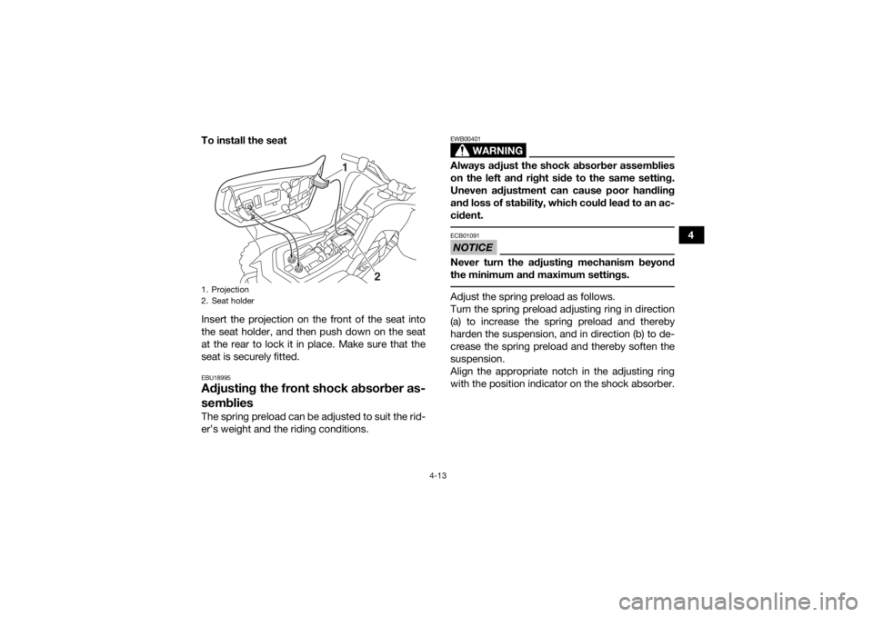
To install the seat
Insert the projection on the front of the seat into
the seat holder, and then push down on the seat
at the rear to lock it in place. Make sure that the
seat is securely fitted.
EBU18995Adjusting the front shock absorber as-
sembliesThe spring preload can be adjusted to suit the rid-
er’s weight and the riding conditions.
WARNING
EWB00401Always adjust the shock absorber assemblies
on the left and right side to the same setting.
Uneven adjustment can cause poor handling
and loss of stability, which could lead to an ac-
cident. NOTICEECB01091Never turn the adjusting mechanism beyond
the minimum and maximum settings. Adjust the spring preload as follows.
Turn the spring preload adjusting ring in direction
(a) to increase the spring preload and thereby
harden the suspension, and in direction (b) to de-
crease the spring preload and thereby soften the
suspension.
Align the appropriate notch in the adjusting ring
with the position indicator on the shock absorber.
1. Projection
2. Seat holder
1
2
UBD362E0.book Page 13 Tuesday, January 31, 2017 5:10 PM
Page 47 of 132
4-15
4
NOTICEECB01091Never turn the adjusting mechanism beyond
the minimum and maximum settings. Adjust the spring preload as follows.
Turn the spring preload adjusting ring in direction
(a) to increase the spring preload and thereby
harden the suspension, and in direction (b) to de-
crease the spring preload and thereby soften the
suspension.
TIPA special wrench can be obtained at a Yamaha
dealer to make this adjustment.
1. Spring preload adjusting ring
2. Position indicator
123 45
2
1
(a)
(b)
1. Special wrenchSpring preload setting:
Minimum (soft):1
Standard: 2
Maximum (hard): 5
1
UBD362E0.book Page 15 Tuesday, January 31, 2017 5:10 PM
Page 126 of 132
10-3
10
Caster angle:3.40 °
Trail: 19.8 mm (0.78 in)Front tire:Type:Tubeless
Size: AT18 x 7-8
Manufacturer/model:
DURO/DI2017Rear tire:Type:Tubeless
Size:
AT18 x 9-8
Manufacturer/model: DURO/DI2016Loading:Maximum loading limit:
82.0 kg (181 lb)
(Total weight of rider, cargo, accessories, and tongue)Tire air pressure (measured on cold tires):Recommended:Front:
24.0 kPa (0.240 kgf/cm², 3.5 psi)
Rear: 24.0 kPa (0.240 kgf/cm², 3.5 psi)
Minimum: Front: 20.7 kPa (0.207 kgf/cm², 3.0 psi) Rear:
20.7 kPa (0.207 kgf/cm², 3.0 psi)
Front wheel:Wheel type:
Panel wheel
Rim size: 8 x 5.5ATRear wheel:Wheel type:
Panel wheel
Rim size: 8 x 5.5ATFront brake:Type:
Mechanical leading, trailing drum brake
Operation: Right hand operationRear brake:Type:
Mechanical leading, trailing drum brake
Operation: Left hand operationFront suspension:Type:
Swing axle
Spring/shock absorber type: Coil spring/oil damper
Wheel travel: 126 mm (5.0 in)
UBD362E0.book Page 3 Tuesday, January 31, 2017 5:10 PM
Page 127 of 132

10-4
10
Rear suspension:Type:Swingarm
Spring/shock absorber type:
Coil spring/oil damper
Wheel travel: 145 mm (5.7 in)Electrical system:Ignition system:
CDI
Charging system: AC magnetoBattery:Model:
GTX5L-BS
Voltage, capacity: 12 V, 4.0 AhBulb voltage, wattage × quantity:Neutral indicator light:
12 V, 3.5 W × 1
Reverse indicator light: 12 V, 3.5 W × 1Fuse:Fuse:
7.5 A
EBU30402For Europe only
The figures quoted are emission levels and are not
necessarily safe working levels. Whilst there is a
correlation between the emission and exposure
levels, this cannot be used reliably to determine
whether or not further precautions are required.
Factors that influence the actual level of exposure
of work-force include the characteristics of the
work room, the other sources of noise, etc. i.e. the
number of machines and other adjacent process-
es, and the length of time for which an operator is
exposed to the noise. Also the permissible expo-
sure level can vary from country. This information,
however, will enable the user of the machine to
make a better evaluation of the hazard and risk.
UBD362E0.book Page 4 Tuesday, January 31, 2017 5:10 PM