Page 79 of 106

Periodic maintenance an d a djustment
6-21
6
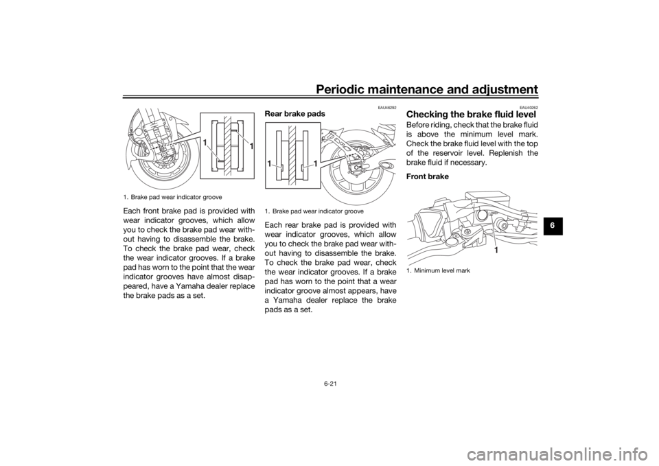
Each front brake pad is provided with
wear indicator grooves, which allow
you to check the brake pad wear with-
out having to disassemble the brake.
To check the brake pad wear, check
the wear indicator grooves. If a brake
pad has worn to the point that the wear
indicator grooves have almost disap-
peared, have a Yamaha dealer replace
the brake pads as a set.
EAU46292
Rear
brake pa ds
Each rear brake pad is provided with
wear indicator grooves, which allow
you to check the brake pad wear with-
out having to disassemble the brake.
To check the brake pad wear, check
the wear indicator grooves. If a brake
pad has worn to the point that a wear
indicator groove almost appears, have
a Yamaha dealer replace the brake
pads as a set.
EAU40262
Checkin g the brake flui d levelBefore riding, check that the brake fluid
is above the minimum level mark.
Check the brake fluid level with the top
of the reservoir level. Replenish the
brake fluid if necessary.
Front brake
1. Brake pad wear indicator groove
1
1
1. Brake pad wear indicator groove
1
1
1. Minimum level mark
1
UBD5E0E0.book Page 21 Wednesday, April 25, 2018 2:23 PM
Page 80 of 106

Periodic maintenance an d a djustment
6-22
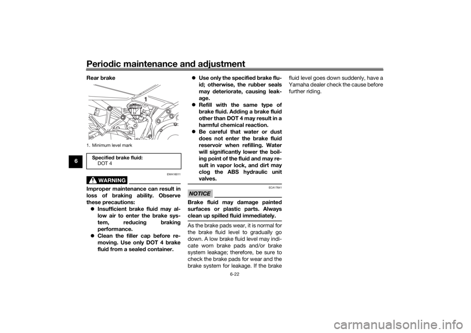
6 Rear
brake
WARNING
EWA16011
Improper maintenance can result in
loss of brakin g a bility. O bserve
these precautions: Insufficient brake flui d may al-
low air to enter the b rake sys-
tem, re ducin g brakin g
performance.
Clean the filler cap before re-
moving . Use only DOT 4 b rake
flui d from a seale d container.
Use only the specified b rake flu-
i d ; otherwise, the ru bber seals
may deteriorate, causin g leak-
a g e.
Refill with the same type of
brake flui d. A ddin g a brake flui d
other than DOT 4 may result in a
harmful chemical reaction.
Be careful that water or dust
d oes not enter the brake flui d
reservoir when refillin g. Water
will si gnificantly lower the boil-
in g point of the flui d an d may re-
sult in vapor lock, an d d ir
t may
clo g the ABS hy draulic unit
valves.
NOTICE
ECA17641
Brake flui d may damag e painted
surfaces or plastic parts. Always
clean up spille d flui d imme diately.As the brake pads wear, it is normal for
the brake fluid level to gradually go
down. A low brake fluid level may indi-
cate worn brake pads and/or brake
system leakage; therefore, be sure to
check the brake pads for wear and the
brake system for leakage. If the brake fluid level goes down suddenly, have a
Yamaha dealer check the cause before further riding.
1. Minimum level markSpecifie d b rake flui d:
DOT 4
1
UBD5E0E0.book Page 22 Wednesday, April 25, 2018 2:23 PM
Page 81 of 106

Periodic maintenance an d a djustment
6-23
6
EAU22734
Chan gin g the brake flui dHave a Yamaha dealer change the
brake fluid every 2 years. In addition,
have the seals of the master cylinders
and brake calipers, as well as the brake
hoses replaced at the intervals listed
below or sooner if they are damaged or
leaking.
Brake seals: every 2 years
Brake hoses: every 4 years
EAU22762
Drive chain slackThe drive chain slack should be
checked before each ride and adjusted
if necessary.
EAU2277G
To check the drive chain slack
1. Place the motorcycle on the side- stand.TIPWhen checking and adjusting the drive
chain slack, there should be no weight
on the motorcycle.2. Shift the transmission into the neutral position.
3. Measure the drive chain slack as shown. 4. If the drive chain slack is incorrect,
adjust it as follows. NOTICE: Im-
proper drive chain slack will
overloa d the en gine as well as
other vital parts of the motorcy-
cle an d can lead to chain slip-
pa ge or b reakag e. If the d rive
chain slack is more than 50.0
mm (1.97 in), the chain can d am-
a g e the frame, swin garm, an d
other parts. To prevent this from
occurrin g, keep the d rive chain
slack within the specified limits.
[ECA17791]
EAU74260
To adjust the drive chain slack
Consult a Yamaha dealer before ad-
justing the drive chain slack. 1. Loosen the axle nut and the lock- nut on each side of the swingarm.
1. Drive chain slack
1
Drive chain slack:5.0–15.0 mm (0.20–0.59 in)
UBD5E0E0.book Page 23 Wednesday, April 25, 2018 2:23 PM
Page 84 of 106
Periodic maintenance an d a djustment
6-26
6
EAU44276
Checkin g an d lu bricatin g the
b rake an d shift pe dalsThe operation of the brake and shift
pedals should be checked before each
ride, and the pedal pivots should be lu-
bricated if necessary.
Brake pe dal
Shift pe dal
EAU23144
Checkin g an d lu bricatin g the
b rake an d clutch leversThe operation of the brake and clutch
levers should be checked before each
ride, and the lever pivots should be lu-
bricated if necessary.
Brake lever
Clutch lever
Recommen ded lu bricant:
Lithium-soap-based grease
UBD5E0E0.book Page 26 Wednesday, April 25, 2018 2:23 PM
Page 85 of 106
Periodic maintenance an d a djustment
6-27
6
EAU23203
Checkin g an d lu bricatin g the
si destan dThe operation of the sidestand should
be checked before each ride, and the
sidestand pivot and metal-to-metal
contact surfaces should be lubricated
if necessary.
WARNING
EWA10732
If the sid estand d oes not move up
an d d own smoothly, have a Yamaha
d ealer check or repair it. Otherwise,
the si destan d coul d contact the
g roun d an d d istract the operator, re-
sultin g in a possi ble loss of control.
EAUM1653
Lu bricatin g the swin garm piv-
otsThe swingarm pivots must be lubricat-
ed by a Yamaha dealer at the intervals
specified in the periodic maintenance
and lubrication chart.
Recommen ded lu bricants:
Brake lever:
Silicone grease
Clutch lever:
Lithium-soap-based grease
Recommen ded lu bricant:
Lithium-soap-based grease
Recommen ded lu bricant:
Lithium-soap-based grease
UBD5E0E0.book Page 27 Wednesday, April 25, 2018 2:23 PM
Page 86 of 106

Periodic maintenance an d a djustment
6-28
6
EAU23273
Checkin g the front forkThe condition and operation of the
front fork must be checked as follows
at the intervals specified in the periodic
maintenance and lubrication chart.
To check the con dition
Check the inner tubes for scratches,
damage and excessive oil leakage.
To check the operation 1. Place the vehicle on a level sur- face and hold it in an upright posi-
tion. WARNING! To avoi d injury,
securely support the vehicle so
there is no dan ger of it fallin g
over.
[EWA10752]
2. While applying the front brake, push down hard on the handle-
bars several times to check if the
front fork compresses and re-
bounds smoothly.
NOTICE
ECA10591
If any d amage is foun d or the front
fork does not operate smoothly,
have a Yamaha dealer check or re-
pair it.
EAU84950
Checkin g the steerin gWorn or loose steering bearings may
cause danger. Therefore, the operation
of the steering must be checked by a
Yamaha dealer at the intervals speci- fied in the periodic maintenance chart.
UBD5E0E0.book Page 28 Wednesday, April 25, 2018 2:23 PM
Page 89 of 106
Periodic maintenance an d a djustment
6-31
6
EAU84650
Replacin g the fusesThe fuse boxes and individual fuses
are located under the rider seat (see
page 3-27) and behind panel A (see
page 6-9).
To access fuse box 1, the main fuse,
and the ABS motor fuse, remove the
rider seat. (See page 3-27.)
TIPTo access the ABS motor fuse, remove
the starter relay cover by pulling it up-
ward.
To access fuse box 2, fuse box 3, the
brake light fuse, and the cruise control
fuse, remove panel A. (See page 6-9.)
1. ABS motor spare fuse
2. ABS motor fuse
3. Fuse box 1
4. Main fuse
1 2
34
1. Fuel injection system fuse
2. ABS solenoid fuse
3. Electronic throttle valve fuse
4. Backup fuse (for clock and immobilizer sys-tem)
5. Heater fuse
6. Spare fuse
1234
65
1. Starter relay cover
2. ABS motor spare fuse
3. ABS motor fuse
1. Fuse box 2
2. Fuse box 3
3. Cruise control fuse
4. Brake light fuse
2 3
1
2
3
41
UBD5E0E0.book Page 31 Wednesday, April 25, 2018 2:23 PM
Page 90 of 106

Periodic maintenance an d a djustment
6-32
6
If a fuse is blown, replace it as follows.1. Turn the main switch off and turn off the electrical circuit in ques-
tion.
2. Remove the blown fuse, and then install a new fuse of the specified
amperage. WARNING! Do not
use a fuse of a hi gher ampera ge
ratin g than recommen ded to avoi
d causin g extensive d am-
a g e to the electrical system an d
possi bly a fire.
[EWA15132]
3. Turn the main switch on and turn
on the electrical circuit in question
to check if the device operates.
4. If the fuse immediately blows again, have a Yamaha dealer
check the electrical system.
1. Signaling system fuse
2. ABS control unit fuse
3. Accessory fuse
4. Ignition fuse
5. Hazard fuse
6. Terminal fuse 1
7. Terminal fuse 2
8. Headlight fuse
9. Right radiator fan motor fuse
10.Left radiator fan motor fuse
11.Spare fuse
11 1
2
3
11
10 9876 5 4
Specifie
d fuses:
Main fuse: 50.0 A
ABS motor fuse:
30.0 A
Cruise control fuse: 1.0 A
Brake light fuse: 1.0 A
Specifie d fuses (fuse box 1):
Fuel injection system fuse: 25.0 A
ABS solenoid fuse: 20.0 A
Electronic throttle valve fuse:
7.5 A
Backup fuse: 7.5 A
Heater fuse: 10.0 A
Specifie d fuses (fuse box 2):
Signaling system fuse:
7.5 A
ABS control unit fuse:
5.0 A
Accessory fuse: 5.0 A
Ignition fuse: 15.0 A
Specifie d fuses (fuse box 3):
Hazard fuse: 7.5 A
Te r m i n a l f u s e 1 : 2.0 A
Te r m i n a l f u s e 2 :
2.0 A
Radiator fan motor fuse: 10.0 A × 2
Headlight fuse: 10.0 A
UBD5E0E0.book Page 32 Wednesday, April 25, 2018 2:23 PM