2018 YAMAHA FJR1300AE fuel consumption
[x] Cancel search: fuel consumptionPage 5 of 122

Table of contents
Safety information ............................1-1
Description ........................................2-1
Left view ..........................................2-1
Right view........................................2-2
Controls and instruments ................2-3
Instrument an d control functions ....3-1
Immobilizer system .........................3-1
Main switch/steering lock ...............3-2
Indicator lights and warning lights ............................................3-4
Cruise control system .....................3-6
Multi-function meter unit .................3-9
D-mode (drive mode) ....................3-22
Handlebar switches.......................3-22
Clutch lever ...................................3-24
Shift pedal .....................................3-24
Brake lever ....................................3-25
Brake pedal ...................................3-25
ABS ...............................................3-26
Traction control system.................3-27
Fuel tank cap.................................3-28
Fuel................................................3-29
Fuel tank overflow hose ................3-30
Catalytic converters .....................3-31
Seats .............................................3-31
Adjusting the rider seat height ......3-33
Storage compartments .................3-35
Accessory box...............................3-36
Adjusting the headlight beams......3-37
Handlebar position ........................3-37
Opening and closing the cowling vents ..........................................3-38
Rear view mirrors ..........................3-39
Adjusting the front and rear
suspension.................................3-40
Sidestand ......................................3-44
Ignition circuit cut-off system........3-45
Auxiliary DC jack ..........................3-47
Cornering lights .............................3-48 For your safety – pre-operation
checks
............................................... 4-1
Operation an d important ri din g
points ................................................. 5-1
Starting the engine.......................... 5-2
Shifting ............................................ 5-3
Tips for reducing fuel consumption................................ 5-4
Engine break-in ............................... 5-5
Parking ............................................ 5-6
Perio dic maintenance an d
a d justment ........................................ 6-1
Owner’s tool kit ............................... 6-2
Periodic maintenance chart for the emission control system.............. 6-3
General maintenance and lubrication chart........................... 6-4
Removing and installing panels ...... 6-7
Checking the spark plugs ............. 6-10
Canister......................................... 6-11
Engine oil and oil filter cartridge ... 6-11
Final gear oil.................................. 6-14
Coolant ......................................... 6-16
Cleaning the air filter element ....... 6-17
Checking the engine idling
speed......................................... 6-19
Checking the throttle grip free
play ............................................ 6-19
Valve clearance ............................. 6-20
Tires .............................................. 6-20
Cast wheels .................................. 6-23
Clutch lever ................................... 6-23
Checking the brake lever free play ............................................ 6-24
Brake light switches ...................... 6-24
Checking the front and rear brake pads................................. 6-25
Checking the brake and clutch fluid levels .................................. 6-26
Changing the brake and clutch fluids .......................................... 6-27
Checking and lubricating the cables ........................................ 6-28
UB96E1E0.book Page 1 Monday, July 10, 2017 10:57 AM
Page 25 of 122
Instrument and control functions
3-11
3
“F” (full) towards “E” (empty) as the fuel
level decreases. When the last seg-
ment starts flashing, refuel as soon as
possible.
When the key is turned to “ON”, all dis-
play segments come on once in order
to test the electrical circuit.
TIP
If a problem is detected in the fuel me-
ter electrical circuit, the fuel meter dis-
play segments will flash repeatedly.
Have a Yamaha dealer check the vehi-
cle.
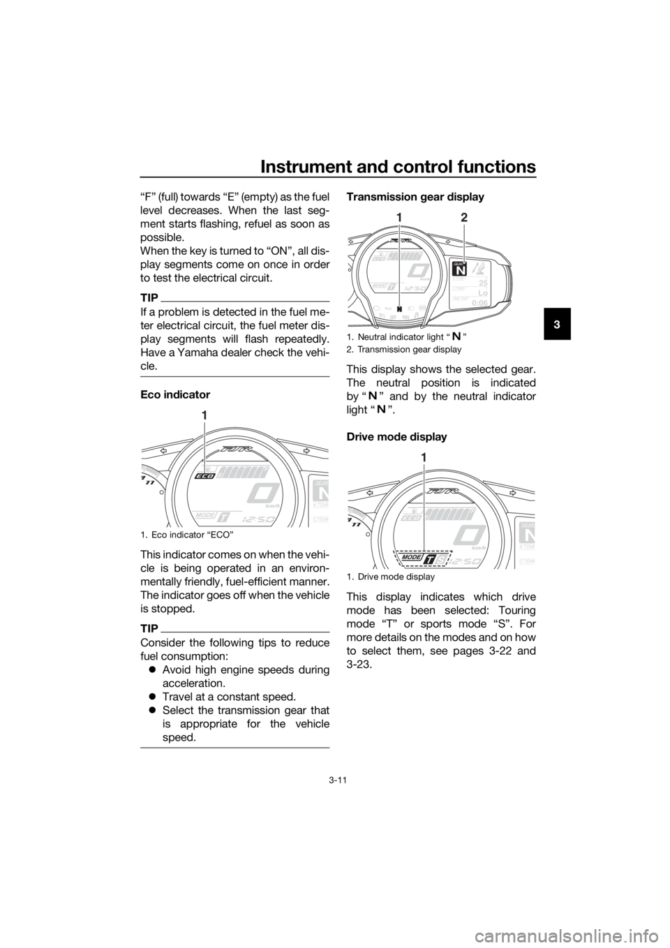
Eco in
dicator
This indicator comes on when the vehi-
cle is being operated in an environ-
mentally friendly, fuel-efficient manner.
The indicator goes off when the vehicle
is stopped.
TIP
Consider the following tips to reduce
fuel consumption: Avoid high engine speeds during
acceleration.
Travel at a constant speed.
Select the transmission gear that
is appropriate for the vehicle
speed.
Transmission gear display
This display shows the selected gear.
The neutral position is indicated
by “ ” and by the neutral indicator
light “ ”.
Drive mo de display
This display indicates which drive
mode has been selected: Touring
mode “T” or sports mode “S”. For
more details on the modes and on how
to select them, see pages 3-22 and
3-23.
1. Eco indicator “ECO”
GEAR
NA.TEMP
C.TEMP
1
1. Neutral indicator light “ ”
2. Transmission gear display
1. Drive mode display
GEARN25A.TEMP ˚C
LoC.TEMP˚C
0:06TIME TRIP
12
GEAR
NA.TEMP
C.TEMP
1
UB96E1E0.book Page 11 Monday, July 10, 2017 10:57 AM
Page 27 of 122

Instrument and control functions
3-13
3
Selectin
g the information display
There are 3 information displays. The
selected information display can be
switched by pushing the select switch.
The following items are shown in the
information displays:
an odometer display
tripmeter displays
a fuel reserve tripmeter display
an estimated traveling range dis-
play
an elapsed time display
an ambient temperature display
a coolant temperature display
an average fuel consumption dis-
play
an instantaneous fuel consump-
tion display
The items shown in each information
display can be selected.
To set or select the items shown, see
page 3-16.
Odometer display:
The odometer shows the total distance
traveled by the vehicle.
Tripmeter displays:
“TRIP-1” and “TRIP-2” show the dis-
tance traveled since they were last set
to zero.
TIP
The odometer will lock at 999999.
The tripmeters will reset and con-
tinue counting after 9999.9 is
reached.
When approximately 5.5 L (1.45 US
gal, 1.21 Imp.gal) of fuel remains in the
fuel tank, the last segment of the fuel
meter starts flashing. In addition, the
information display will automatically
change to the fuel reserve tripmeter
mode “TRIP-F” and start counting the
distance traveled from that point.
1. Information display
2. Display–1
3. Display–2
4. Display–3
GEARN
5.0TRIP-1 km
7.0TRIP-2km
km
20ODO
GEARN
11RANGE km
12.3FUEL AVG km/L
km/L
12.3CRNT FUEL
GEARN
25A.TEMP ˚C
LoC.TEMP ˚C
0:06TIME TRIP
3
421
20
ODOkm
5.0
TRIP-1km
7.0
TRIP-2km
GEAR
4
3.4
TRIP-F km
UB96E1E0.book Page 13 Monday, July 10, 2017 10:57 AM
Page 29 of 122

Instrument and control functions
3-15
3
If the message “Hi” flashes, stop the
vehicle, then stop the engine, and let
the engine cool. (See page 6-37.)
TIP
The selected information display can-
not be switched while the message
“Hi” is flashing.
NOTICE
ECA10022
Do not continue to operate the en-
g
ine if it is overheatin g.
Average fuel consumption display:
The average fuel consumption display
modes “km/L”, “L/100km” or “MPG”
show the average fuel consumption
since the display was last reset.
The “km/L” display shows the av-
erage distance that can be trav-
eled on 1.0 L of fuel.
The “L/100km” display shows the
average amount of fuel necessary
to travel 100 km.
The “MPG” display shows the av-
erage distance that can be trav-
eled on 1.0 Imp.gal of fuel. To reset the average fuel consumption
display, use the select switch to select
the information display that contains
the average fuel consumption display.
Push the “RESET” button briefly so
that the average fuel consumption dis-
play flashes, and then push the “RE-
SET” button again for 2 seconds while
the display is flashing.
TIP
After resetting the average fuel con-
sumption display, “_ _._” will be shown
for that display until the vehicle has
traveled 1 km (0.6 mi).
NOTICE
ECA15474
If there is a malfunction, “– –.–” will
b
e continuously displaye d. Have a
Yamaha dealer check the vehicle.
Instantaneous fuel consumption dis-
play:
The instantaneous fuel consumption
display modes “km/L”, “L/100km” or
“MPG” show the fuel consumption un-
der the current riding conditions.
The “km/L” display shows the dis-
tance that can be traveled on 1.0 L
of fuel.
The “L/100km” display shows the
amount of fuel necessary to travel
100 km.
The “MPG” display shows the dis-
tance that can be traveled on
1.0 Imp.gal of fuel.
GEAR
4
Hi
C.TEMP ˚C
12.3
FUEL AVG km/L12.3
CRNT FUEL km/L
UB96E1E0.book Page 15 Monday, July 10, 2017 10:57 AM
Page 68 of 122

Operation and important rid ing points
5-4
5 clutch lever in, use the brakes to
slow the motorcycle, and continue
to downshift as necessary.
4. Once the motorcycle has stopped, the transmission can be
shifted into the neutral position.
The neutral indicator light should
come on and then the clutch lever
can be released.
WARNING
EWA17380
Improper brakin g can cause
loss of control or traction. Al-
ways use b oth brakes an d apply
them smoothly.
Make sure that the motorcycle
and the en gine have sufficiently
slowe d b efore shiftin g to a low-
er gear. En gag in g a lower gear
when the vehicle or en gine
speed is too hi gh coul d make
the rear wheel lose traction or
the en gine to over-rev. This
coul d cause loss of control, an
acci dent an d injury. It coul d also
cause en gine or drive train dam-
a g e.
EAU64150Recommen ded shift points
The recommended shift points during
acceleration and deceleration are
shown in the table below.
EAU16811
Tips for re ducin g fuel con-
sumption
Fuel consumption depends largely on
your riding style. Consider the follow-
ing tips to reduce fuel consumption:
Shift up swiftly, and avoid high en-
gine speeds during acceleration.
Do not rev the engine while shift-
ing down, and avoid high engine
speeds with no load on the en-
gine.
Turn the engine off instead of let-
ting it idle for an extended length
of time (e.g., in traffic jams, at traf-
fic lights or at railroad crossings).
Shift up points:
1st → 2nd: 20 km/h (12 mph)
2nd → 3rd: 30 km/h (19 mph)
3rd → 4th: 40 km/h (25 mph)
4th → 5th: 50 km/h (31 mph)
5th → 6th: 60 km/h (37 mph)
Shift down points:
6th → 5th: 45 km/h (28 mph)
5th → 4th: 35 km/h (22 mph)
4th → 3rd: 25 km/h (16 mph)
UB96E1E0.book Page 4 Monday, July 10, 2017 10:57 AM
Page 118 of 122

10-1
10
Index
A
ABS ....................................................... 3-26
ABS warning light ................................... 3-5
Accessory box ...................................... 3-36
Air filter element, cleaning .................... 6-17
Auxiliary DC jack ................................... 3-47
B
Battery .................................................. 6-32
Brake and clutch fluid levels,
checking ............................................. 6-26
Brake and clutch fluids, changing ........ 6-27
Brake and clutch levers, checking and
lubricating ........................................... 6-29
Brake and shift pedals, checking and
lubricating ........................................... 6-29
Brake lever ............................................ 3-25
Brake lever free play, checking............. 6-24
Brake light switches.............................. 6-24
Brake pedal........................................... 3-25
C
Cables, checking and lubricating ......... 6-28
Canister................................................. 6-11
Care ........................................................ 7-1
Catalytic converters .............................. 3-31
Centerstand and sidestand, checking
and lubricating .................................... 6-30
Clutch lever ................................. 3-24, 6-23
Coolant ................................................. 6-16
Cornering lights .................................... 3-48
Cowling vents, opening and closing ..... 3-38
Cruise control indicator lights ................. 3-4
Cruise control switches ........................ 3-23
Cruise control system ............................. 3-6
D
Diagnostic connector.............................. 9-2
Dimmer/Pass switch ............................. 3-22
D-mode (drive mode) ............................ 3-22
E
Engine break-in....................................... 5-5
Engine idling speed, checking .............. 6-19
Engine oil and oil filter cartridge ........... 6-11
Engine serial number .............................. 9-1
Engine trouble warning light ................... 3-4
F
Final gear oil.......................................... 6-14
Front and rear brake pads, checking.... 6-25
Front fork, checking .............................. 6-30
Fuel ....................................................... 3-29
Fuel consumption, tips for reducing ....... 5-4
Fuel tank cap ........................................ 3-28 Fuel tank overflow hose ....................... 3-30
Fuses, replacing ................................... 6-33
H
Handlebar position, adjusting .............. 3-37
Handlebar switches .............................. 3-22
Hazard switch....................................... 3-23
Headlight beams, adjusting.................. 3-37
High beam indicator light ....................... 3-4
Horn switch .......................................... 3-23
I
Identification numbers ............................ 9-1
Ignition circuit cut-off system............... 3-45
Immobilizer system ................................ 3-1
Immobilizer system indicator light.......... 3-5
Indicator lights and warning lights ......... 3-4
M
Main switch/steering lock....................... 3-2
Maintenance and lubrication, periodic ... 6-4
Maintenance, emission control
system.................................................. 6-3
Matte color, caution ............................... 7-1
Menu switch ......................................... 3-23
Model label ............................................. 9-1
Multi-function meter unit ........................ 3-9
N
Neutral indicator light ............................. 3-4
O
Oil level warning light ............................. 3-4
P
Panels, removing and installing.............. 6-7
Parking ................................................... 5-6
Part locations ......................................... 2-1
R
Rear view mirrors ................................. 3-39
Rider seat height, adjusting.................. 3-33
S
Safety information .................................. 1-1
Seats .................................................... 3-31
Select switch ........................................ 3-23
Shifting ................................................... 5-3
Shift pedal ............................................ 3-24
Sidestand ............................................. 3-44
Spark plugs, checking .......................... 6-10
Specifications ......................................... 8-1
Starting the engine ................................. 5-2
Steering, checking................................ 6-31
Stop/Run/Start switch .......................... 3-23
Storage ................................................... 7-4
Storage compartments ........................ 3-35
UB96E1E0.book Page 1 Monday, July 10, 2017 10:57 AM