Page 19 of 78

Instrument and control functions
3-3
3 If the warning light does not come on
initially when the key is turned to “ ”,
or if the warning light remains on, have
a Yamaha dealer check the electrical
circuit.
NOTICE
ECA10022
Do not continue to operate the en-
gine if it is overheating.TIPIf the engine overheats, see page 6-30
for further instructions.
EAU78310
Engine trouble warning light “ ”
This warning light comes on if a prob-
lem is detected in the engine or other
vehicle control system. If this occurs,
have a Yamaha dealer check the on-
board diagnostic system.
The electrical circuit of the warning
light can be checked by turning the key
to “ ”. The warning light should come
on for a few seconds, and then go off.
If the warning light does not come on
initially when the key is turned to “ ”,
or if the warning light remains on, have
a Yamaha dealer check the vehicle.
EAUM3131
Multi-function displayTIPThe multi-function display performs
the following self-test for three sec-
onds in order to check the electrical
circuit.
The speedometer digits display
from 0 to 80, and then from 80 to
0 in kilometers. If the speedometer
is set to miles, the digits will dis-
play from 0 to 50, and then from
50 to 0.All LCD segments and warning
lights come on and then go off.
WARNING
EWA12313
Be sure to stop the vehicle before
making any setting changes to the
multi-function display. Changing
settings while riding can distract the
operator and increase the risk of an
accident.The multi-function display is equipped
with the following:
a digital clock
a digital speedometer (which
shows riding speed)
an odometer (which shows the to-
tal distance traveled)
a tripmeter (which shows the dis-
tance traveled since it was last set
to zero)
a fuel reserve tripmeter (which
shows the distance traveled on
the fuel reserve)
an oil change indicator (which
shows when the engine oil should
be changed)
a fuel gauge
a self-diagnosis device
1. Speedometer
2. Oil change indicator “OIL CHANGE”
3. Clock
4. “RESET/SELECT” button
5. Odometer/tripmeters/fuel reserve tripmeter
6. Fuel gaugeZAUM1063
O
I
L CHA
NGE56
1
3
42
U1GBE1E0.book Page 3 Tuesday, October 17, 2017 11:45 AM
Page 20 of 78

Instrument and control functions
3-4
3
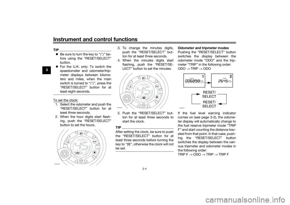
TIPBe sure to turn the key to “ ” be-
fore using the “RESET/SELECT”
button.
For the U.K. only: To switch the
speedometer and odometer/trip-
meter displays between kilome-
ters and miles, when the main
switch is turned to “ ”, press the
“RESET/SELECT” button for at
least eight seconds.To set the clock:1. Select the odometer and push the
“RESET/SELECT” button for at
least three seconds.
2. When the hour digits start flash-
ing, push the “RESET/SELECT”
button to set the hours.3. To change the minutes digits,
push the “RESET/SELECT” but-
ton for at least three seconds.
4. When the minutes digits start
flashing, push the “RESET/SE-
LECT” button to set the minutes.
5. Push the “RESET/SELECT” but-
ton for at least three seconds to
start the clock.
TIPAfter setting the clock, be sure to push
least three seconds before turning the
key to Ž, otherwise the clock will not
be set.
Odometer and tripmeter modes
Pushing the “RESET/SELECT” button
switches the display between the
odometer mode “ODO” and the trip-
meter “TRIP” in the following order:
ODO → TRIP → ODO
If the fuel level warning indicator
comes on (see page 3-2), the odome-
ter display will automatically change to
the fuel reserve tripmeter mode “TRIP
F” and start counting the distance trav-
eled from that point. In that case, push-
ing the “RESET/SELECT” button
switches the display between the vari-
ous tripmeter and odometer modes in
the following order:
TRIP F → ODO → TRIP → TRIP F
ZAUM1064
OIL CHA
NGE
ZAUM1065
O
IL
CHAN
GE
ZAUM0914
RESET/
SELECT
RESET/
SELECT
U1GBE1E0.book Page 4 Tuesday, October 17, 2017 11:45 AM
Page 23 of 78
Instrument and control functions
3-7
3
EAU12902
Front brake leverThe front brake lever is located on the
right side of the handlebar. To apply
the front brake, pull this lever toward
the throttle grip.
EAU12952
Rear brake leverThe rear brake lever is located on the
left side of the handlebar. To apply the
rear brake, pull this lever toward the
handlebar grip.
EAUM3261
Fuel tank capTo remove the fuel tank cap
1. Open the passenger seat. (See
page 3-11.)
2. Turn the fuel tank cap counter-
clockwise and pull it off.
To install the fuel tank cap
1. Insert the fuel tank cap into the
tank opening and turn it clock-
wise.
2. Close the passenger seat.
1. Front brake lever
1
ZAUM0791
1. Rear brake lever
1
ZAUM0085
1. Fuel tank capZAUM1068
1
U1GBE1E0.book Page 7 Tuesday, October 17, 2017 11:45 AM
Page 27 of 78
Instrument and control functions
3-11
3
EAUM2831
SeatsPassenger seat
To open the passenger seat1. Place the scooter on the center-
stand.
2. Insert the key into the main switch,
and then turn it counterclockwise.
TIPDo not push inward when turning the
key.3. The passenger seat will fold up
automatically.NOTICE
ECAM1111
Be sure to remove all objects on the
passenger seat before opening. Ob-
jects left on the seat may fall and
break or be damaged when the seat
opens.
To close the passenger seat1. Fold the passenger seat down,
and then push it down to lock it in
place.
2. Remove the key from the main
switch if the scooter will be left un-
attended.TIPMake sure that the passenger seat is
properly secured before riding.Rider seat
To open the rider seat1. Open the passenger seat.
2. Fold the rider seat up.
1. Passenger seat
2. Rider seatZAUM0926
2 1
1. Open.ZAUM0943
1. Passenger seatZAUM1070
1
U1GBE1E0.book Page 11 Tuesday, October 17, 2017 11:45 AM
Page 62 of 78
Periodic maintenance and adjustment
6-27
6
EAU24135
Replacing the tail/brake light
bulb1. Remove the tail/brake light lens by
removing the screws.
2. Remove the burnt-out bulb by
pushing it in and turning it coun-
terclockwise.
3. Insert a new bulb into the socket,
push it in, and then turn it clock-
wise until it stops.
4. Install the lens by installing the
screws. NOTICE: Do not over-
tighten the screws, otherwise
the lens may break.
[ECA10682]EAU24205
Replacing a turn signal light
bulb1. Remove the turn signal light lens
by removing the screw.
2. Remove the burnt-out bulb by
pushing it in and turning it coun-
terclockwise.3. Insert a new bulb into the socket,
push it in, and then turn it clock-
wise until it stops.
4. Install the lens by installing the
screw. NOTICE: Do not over-
tighten the screw, otherwise the
lens may break.
[ECA11192]
ZAUM0937
ZAUM0938ZAUM0939
U1GBE1E0.book Page 27 Tuesday, October 17, 2017 11:45 AM
Page 65 of 78

Periodic maintenance and adjustment
6-30
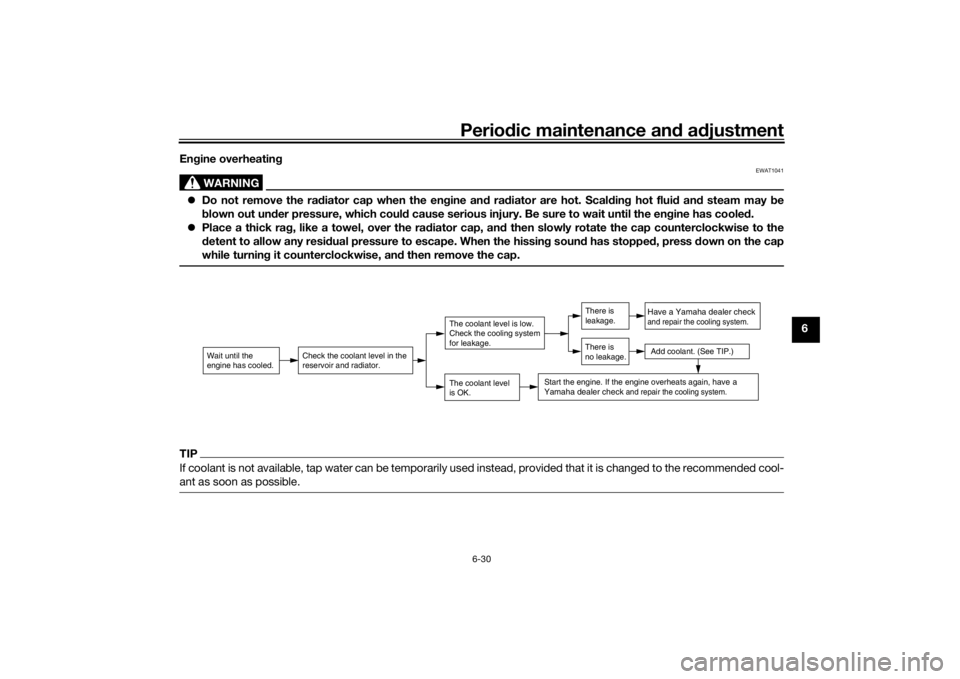
6 Engine overheating
WARNING
EWAT1041
Do not remove the radiator cap when the engine and radiator are hot. Scalding hot fluid and steam may be
blown out under pressure, which could cause serious injury. Be sure to wait until the engine has cooled.
Place a thick rag, like a towel, over the radiator cap, and then slowly rotate the cap counterclockwise to the
detent to allow any residual pressure to escape. When the hissing sound has stopped, press down on the cap
while turning it counterclockwise, and then remove the cap.TIPIf coolant is not available, tap water can be temporarily used instead, provided that it is changed to the recommended cool-
ant as soon as possible.
Wait until the
engine has cooled.
Check the coolant level in the
reservoir and radiator.
The coolant level
is OK.The coolant level is low.
Check the cooling system
for leakage.
Have a Yamaha dealer checkand repair the cooling system.Add coolant. (See TIP.)
Start the engine. If the engine overheats again,
have a
Yamaha dealer check
and repair the cooling system.
There is
leakage.
There is
no leakage.
U1GBE1E0.book Page 30 Tuesday, October 17, 2017 11:45 AM