2018 VOLVO XC60 T8 ECO mode
[x] Cancel search: ECO modePage 348 of 674

||
DRIVER SUPPORT
* Option/accessory.
346
Examples of further limitations
• Dirt, ice and snow covering the sensors may reduce functionality and prevent the systemfrom providing warnings. For additional infor-mation, see the section "Recommendedmaintenance for Cross Traffic Alert".
• CTA is automatically deactivated if a trailer,bicycle holder or similar is connected to thevehicle's electrical system.
• For CTA to function optimally, bicycle hold-ers, luggage racks or similar should not bemounted on the vehicle's towbar.
Related information
•
Cross Traffic Alert
* (p. 344)
Recommended maintenance forCross Traffic Alert
• For optimal performance, it is important to keep the areas in front of the sensors clean.
• Do not attach any objects, tape or decals tothe surface of the sensors.
Keep this area clean (on both the left and right sides of the vehicle) 91
.
The CTA sensors are located on the inside of each of the rear fenders/bumpers and are also used by the BLIS 92
and Rear Collision Warning
functions.
CAUTION
Repair of BLIS and CTA components or repainting of the bumper may only be per-formed by a workshop – an authorized Volvoworkshop is recommended.
Related information
• Cross Traffic Alert
* (p. 344)
• BLIS
* (p. 339)
• Rear Collision Warning (p. 338)
91
Note: This illustration is general and details may vary depending on model.
92 Blind Spot Information
Page 357 of 674

DRIVER SUPPORT
}}
355
Selecting guidance to a rest area ifthe Driver Alert Control warning hasbeen givenThe
Rest Stop Guidance function can be
switched on or off.
When the guide is activated, it will automatically display suggestions for a suitable place to take abreak if the DAC warning is given. To select
Rest Stop Guidance:
1. Tap
Settings in the center display's Top
view.
2. Select
My CarIntelliSafeDriver Alert
Control.
3. Select/deselect
Rest Stop Guidance to
activate/deactivate the function.
Related information
• Driver Alert Control (p. 353)
Driver Alert Control limitations
Driver Alert Control (DAC) functionality may be reduced in certain situations.
In certain situations, the system may provide a warning even if it has not detected a change indriving behavior, e.g.:
• in strong crosswinds
• on grooved road surfaces.
WARNING
In certain cases, driving behavior might not be affected despite the driver's fatigue – whenusing the Pilot Assist function – resulting inthe driver not getting a warning from DAC. It is therefore very important to always stop and take a break at the slightest sign of fati-gue, regardless of whether the DAC functionhas issued a warning or not.
NOTE
The function uses the vehicle's camera unit, which has some general limitations – see thesection "Camera unit limitations".
Related information
• Driver Alert Control (p. 353)
Lane Keeping Aid
Lane Keeping Aid (LKA 106
) is designed to
actively steer the vehicle on freeways, highways and other major roads to help the driver reducethe risk of the vehicle unintentionally veering outof the lane.
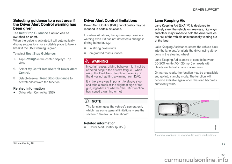
Lake Keeping Assistance steers the vehicle back into the lane and/or alerts the driver using vibra-tions in the steering wheel. Lane Keeping Aid is active at speeds between 65-200 km/h (40-125 mph) on roads withclearly visible traffic lane marker lines. On narrow roads, the function may be unavailable and go into standby mode. The function willbecome available again when the road becomessufficiently wide.
A camera monitors the road/traffic lane's marker lines.
106 Lane Keeping Aid
Page 360 of 674

DRIVER SUPPORT
358
Activating/deactivating LaneKeeping Aid The Lane Keeping Aid (LKA110
) function can be
switched On or Off.
On/OffPress the Lane Keeping Aidbutton in the center display's Function view.
• GREEN button indicator light - LKA is acti- vated.
• GRAY button indicator light - LKA is deacti-vated.
Related information
•Lane Keeping Aid (p. 355)
Selecting type of assistance forLane Keeping Aid
The driver can determine what types of assis- tance LKA 111
should provide if the vehicle veers
from its lane.
1. Select SettingsMy CarIntelliSafe in
the center display's Top view.
2. Under
Lane Keeping Aid Mode, select
what assistance LKA should provide:
•
Assist the driver will receive steering
assistance but no warning.
•
Both - the driver will receive both steering
assistance and a warning.
•
Warning - the driver will only receive a
warning.
Related information
• Lane Keeping Aid (p. 355)
Lane Keeping Aid limitations
In certain demanding driving conditions, Lane Keeping Aid may not be able to properly assistthe driver. In these situations, it is recommendedthat the function be deactivated.
Examples of such situations include:
• road work
• winter driving conditions
• poor road surfaces
• a very sporty driving style
• bad weather with reduced visibility
• roads with indistinct or no lane markings
• sharp edges or lines other than the lane's side markings
• when the power steering works at reducedpower - e.g. during cooling due to overheat-ing (see section "Speed-dependent steeringforce").
NOTE
The function uses the vehicle's camera unit, which has some general limitations – see thesection "Camera unit limitations".
110
Lane Keeping Aid
111 Lane Keeping Aid
Page 362 of 674

DRIVER SUPPORT
360
Lane Keeping Aid symbols andmessages
A number of symbols and messages related to Lane Keeping Aid LKA 112
may be displayed in
the instrument panel.
Some examples of symbols and messages are shown in the table below.
SymbolMessageMeaning
Driver support system Reduced functionality Service requiredThe system is not functioning as intended. Contact a workshop ‒ an authorized Volvo work-
shop is recommended.
Windscreen sensor Sensor blocked, see Owner's manualThe camera's ability to detect the lane in front of the vehicle is reduced.
Lane Keeping Aid Apply steeringLKA's steering assistance is disabled when the driver's hands are not on the wheel. Follow the instructions and steer the vehicle.
Lane Keeping Aid Standby until steering appliedLKA will go into standby mode until the driver begins steering the vehicle again.
112 Lane Keeping Aid
Page 377 of 674

DRIVER SUPPORT
* Option/accessory.375
CAUTION
Objects such as chains, thin and glossy poles or low obstacles may end up in the "signalshadow" and then go temporarily undetectedby the sensors – the pulsating tone may thenunexpectedly stop instead of becoming aconstant tone as expected. The sensors cannot detect high objects, such as protruding ramps.
• In such situations, pay extra attention andmaneuver/drive the vehicle very slowly orstop the current parking maneuver –there may be a high risk of damage tothe vehicle or other objects since infor-mation from the sensors is not alwaysreliable in such situations.
CAUTION
In some circumstances, the Park Assist Sys- tem may produce false warnings due to exter-nal sound sources with the same ultrasonicfrequencies as those the system works with. Examples of such sources are horns, wet tires on asphalt, pneumatic brakes, exhaust noisefrom motorcycles, etc.
NOTE
When a trailer hitch is configured with the vehicle electrical system, the trailer hitch pro-trusion is included when the function meas-ures the distance to objects behind the vehi-cle.
Related information
•
Park Assist
* (p. 372)
Recommended maintenance forPark Assist
For Park Assist to function optimally, its sensors must be cleaned regularly with water and carwashing detergent.
Location of the Park Assist sensors 114
.
NOTE
Dirt, ice and snow covering the sensors could cause false warnings, reduced function, or nofunction.
Related information
• Park Assist
* (p. 372)
114
Note: This illustration is general and details may vary depending on model.
Page 379 of 674

DRIVER SUPPORT
* Option/accessory.377
Park Assist Camera *
The Park Assist Camera can help provide the driver when maneuvering in tight spaces by alert-ing the driver to obstacles using the camerascreen and graphics in the center display.
The Park Assist Camera is a support function that is automatically activated when reverse gearis engaged. It can also be started manually fromthe center display.
Example camera view 115
.
Zoom116
- zoom in/out
360° view* - activate/deactivate all cameras
PAS* - activate/deactivate Parking Assist
Lines - activate/deactivate trajectory lines
Towbar* - activate/deactivate trajectory lines
for towbar *117
CTA*
- activate/deactivate Cross Traffic Alert
WARNING
• The Parking Camera function is supple- mentary driver support intended to facili-tate driving and help make it safer – itcannot handle all situations in all traffic,weather and road conditions.
• The parking cameras have dead/blindspots where objects cannot be detected.
• Pay particular attention to people andanimals near the vehicle.
• Objects/obstacles may be closer to thevehicle than they appear on the screen.
• The parking cameras are not a substitutefor the driver's attention and judgment.The driver is always responsible forensuring the vehicle is driven in a safemanner, at the appropriate speed, with anappropriate distance to other vehicles,and in accordance with current trafficrules and regulations.
Related information
•Park Assist Camera views (p. 378)
• Park Assist Camera trajectory lines (p. 379)
• Sensor field from Park Assist for Park AssistCamera (p. 381)
• Starting the Park Assist Camera (p. 382)
• Park Assist Camera limitations (p. 382)
• Recommended maintenance of the ParkAssist Camera (p. 384)
• Recommended maintenance of the ParkAssist Camera (p. 384)
• Park Assist Camera symbols and messages(p. 385)
115
The illustration is generic - details may vary according to vehicle model.
116 The trajectory lines will not be displayed when zooming in.
117 Not available in all markets.
Page 395 of 674

DRIVER SUPPORT
* Option/accessory.393
Recommended maintenance forPark Assist Pilot For Park Assist Pilot (PAP 128
) to function opti-
mally, its sensors must be cleaned regularly with water and car washing detergent.
Location of the Park Assist sensors 129
.
NOTE
Dirt, ice and snow covering the sensors could cause false warnings, reduced function, or nofunction.
Related information
• Park Assist Pilot
* (p. 386)
128
Park Assist Pilot
129 Note: This illustration is general and details may vary depending on model.
Page 398 of 674

HYBRID INFORMATION
396
General information about TwinEngine
Twin Engine vehicles are driven just like any other vehicle, but certain functions differ from avehicle powered exclusively by gasoline. Theelectric motor powers the vehicle primarily at lowspeeds; the gasoline engine is used at higherspeeds or during more active driving.
The instrument panel displays Twin Engine-spe- cific information - charging information, selecteddrive mode, distance to discharged battery andhybrid battery charge level. Different drive modes can be selected while driv- ing, e.g. electric power only or, if more power isneeded, a combination of electric and gasolinepower. The vehicle calculates the optimal combi-nation of driveability, driving experience, environ-mental impact and fuel economy for the selecteddrive mode. In order to function optimally, the hybrid battery (and its electrical drive systems) and the gasolineengine (and its drive systems) must be at thecorrect operating temperature. Battery capacitycan be considerably reduced if the battery is toocold or too hot. Preconditioning prepares thevehicle's drive systems and passenger compart-ment before driving to help reduce both wear andenergy consumption. It also helps increase thehybrid battery's range. The hybrid battery, which powers the electric motor, is recharged using the charging cable. Itcan also be recharged during light braking and through engine braking in gear position
B. The
combustion engine can also help recharge thehybrid battery.
Important
No electrical current
Keep in mind that if there is no electrical current to the vehicle, i.e. the ignition is switched off orthe start battery is discharged, certain functionssuch as brakes, power steering, etc. will not work.
WARNING
If the vehicle does not have electrical current and both the electric motor and the gasolineengine are switched off, the brakes cannot beused to stop the vehicle.
Towing not permitted
Never tow a Twin Engine vehicle behind another vehicle, as this could damage the electric motor.
Exterior engine noise
WARNING
Keep in mind that the vehicle does not emit any engine noise when using the electricmotor and may therefore be difficult to detectfor children, pedestrians, cyclists or animals.This is especially true at low speeds, e.g. inparking lots.
High-voltage electrical current
WARNING
Several components in the vehicle work with high voltage that can be hazardous in case ofan incorrect procedure. These componentsand any orange wiring in the vehicle may onlybe handled by trained and qualified Volvoservice technicians.
Do not touch anything that is not clearly descri- bed in this Owner's Manual.
Related information
• Charging the hybrid battery (p. 397)
• Hybrid gauge (p. 83)
• Drive modes (p. 435)
• Starting and stopping preconditioning(p. 222)
• Hybrid battery (p. 609)
• Factors affecting electric motor range(p. 448)
• Gear selector positions for automatic trans-missions (p. 429)
• Towing using a towline (p. 466)