2018 VOLVO XC60 T8 fog light
[x] Cancel search: fog lightPage 158 of 674
||
LIGHTING
156The rear fog light turns off automatically when the start knob is turned clockwise to turn off theignition or when the lighting ring is turned to the
or position.
NOTE
Regulations concerning rear fog light use vary from country to country.
Related information
•
Lighting panel and controls (p. 148)
• Ignition modes (p. 417)
Brake lights The brake lights are automatically illuminated when braking.
The brake lights illuminate when the brake pedal is depressed. They also illuminate when thebrakes are automatically applied by one of thedriver support systems.
Related information
•
Emergency brake lights (p. 156)
• Brake functions (p. 419)
Emergency brake lights
The emergency brake lights are activated to warn following vehicles of hard braking. This function causes an additional taillight on each side of the vehicle to illuminate.
The emergency brake lights are activated in the event of hard braking or if the ABS system isactivated and the vehicle is traveling at a highspeed. After the driver decelerates to a low speed and then releases the brake, the brake lights resumetheir normal brightness.
Related information
• Brake lights (p. 156)
• Brakes (p. 419)
• Hazard warning flashers (p. 157)
Page 215 of 674
CLIMATE CONTROL
213
NOTE
It is possible to change the temperature and blower speed without deactivating automaticclimate control. Automatic climate control isdeactivated when the air distribution ischanged manually or when the max defrosteris activated.
Related information
•Climate system controls (p. 208)
Activating and deactivatingrecirculation
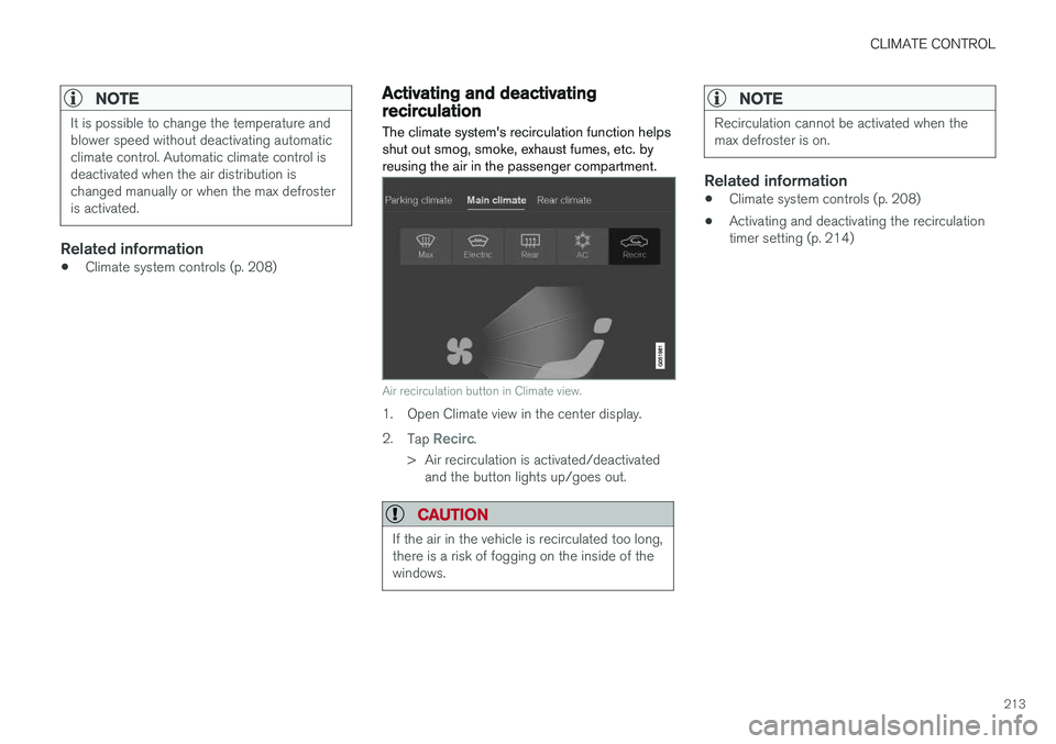
The climate system's recirculation function helps shut out smog, smoke, exhaust fumes, etc. byreusing the air in the passenger compartment.
Air recirculation button in Climate view.
1. Open Climate view in the center display. 2. Tap
Recirc.
> Air recirculation is activated/deactivated and the button lights up/goes out.
CAUTION
If the air in the vehicle is recirculated too long, there is a risk of fogging on the inside of thewindows.
NOTE
Recirculation cannot be activated when the max defroster is on.
Related information
• Climate system controls (p. 208)
• Activating and deactivating the recirculation timer setting (p. 214)
Page 220 of 674
CLIMATE CONTROL
218
Setting the blower speed for the
front seats3
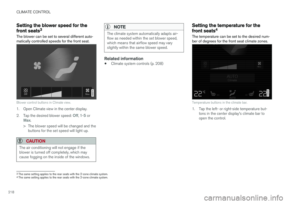
The blower can be set to several different auto- matically controlled speeds for the front seat.
Blower control buttons in Climate view.
1. Open Climate view in the center display. 2. Tap the desired blower speed:
Off, 1-5 orMax.
> The blower speed will be changed and the buttons for the set speed will light up.
CAUTION
The air conditioning will not engage if the blower is turned off completely, which maycause fogging on the inside of the windows.
NOTE
The climate system automatically adapts air- flow as needed within the set blower speed,which means that airflow speed may varyslightly within the same blower speed.
Related information
• Climate system controls (p. 208)
Setting the temperature for the
front seats4
The temperature can be set to the desired num- ber of degrees for the front seat climate zones.
Temperature buttons in the climate bar.
1. Tap the left- or right-side temperature but- tons in the center display's climate bar to open the control.
3The same setting applies to the rear seats with the 2-zone climate system.
4 The same setting applies to the rear seats with the 2-zone climate system.
Page 315 of 674
DRIVER SUPPORT
}}}}
313
Deactivation of the Auto-hold brake function
In certain situations, Auto-hold will be deactivated when the vehicle is at a standstill and Pilot Assistwill go into standby mode. This means that thebrakes will be released and the vehicle couldbegin to roll. The driver must actively apply thebrakes to keep the vehicle stationary. This can occur if:
• the driver depresses the brake pedal
• the parking brake is applied
• the gear selector is moved to the
P, N or R
positions
• the driver puts Pilot Assist in standby mode.
Auto Activate Parking BrakeIn certain situations, the parking brake will be applied to keep the vehicle at a standstill. This occurs if Pilot Assist is keeping the vehicle stationary using the brakes and:
• the driver opens the door or unbuckleshis/her seat belt
• Pilot Assist has kept the vehicle at a stand-still for more than approx. 5 minutes
• the brakes overheat
• the driver switches off the engine manually.
Related information
•Pilot Assist (p. 301)
Pilot Assist limitations
Pilot Assist functionality may be reduced in cer- tain situations.
Pilot Assist is a driver support function designed to simplify driving and assist the driver in manysituations. However, the driver is always responsi-ble for maintaining a suitable distance to vehiclesor objects around it and ensuring that the vehicleis correctly positioned in the traffic lane.
WARNING
In some situations, Pilot Assist may have trou- ble helping the driver properly or may bedeactivated automatically – we advise againstusing Pilot Assist in such cases. Examples ofsuch situations include:
• the lane markings are worn, missing or cross each other.
• lane division is unclear, for example, whenthe lanes divide or merge or at exits orwhen there are multiple sets of markings.
• edges or other lines than lane markingsare present on or near the road, e.g.curbs, joints or repairs to the road sur-face, edges of barriers, roadside edges orstrong shadows.
• the lane is narrow or winding.
• the lane contains ridges or holes.
• weather conditions are poor, e.g. rain,snow or fog or slush or reduced visibilitywith poor light conditions, backlighting,wet road surface, etc.
The driver should also note that Pilot Assist has the following limitations: • High curbs, roadside barriers, temporary obstacles (traffic cones, safety barriers,etc.) are not detected. Alternatively, theymay be detected incorrectly as lane mark-ings, with a subsequent risk of contactbetween the vehicle and such obstacles.
Page 324 of 674
DRIVER SUPPORT
322
Camera limitations
The camera used by several of the driver support functions has certain limitations, which alsoaffect the functions using the camera.
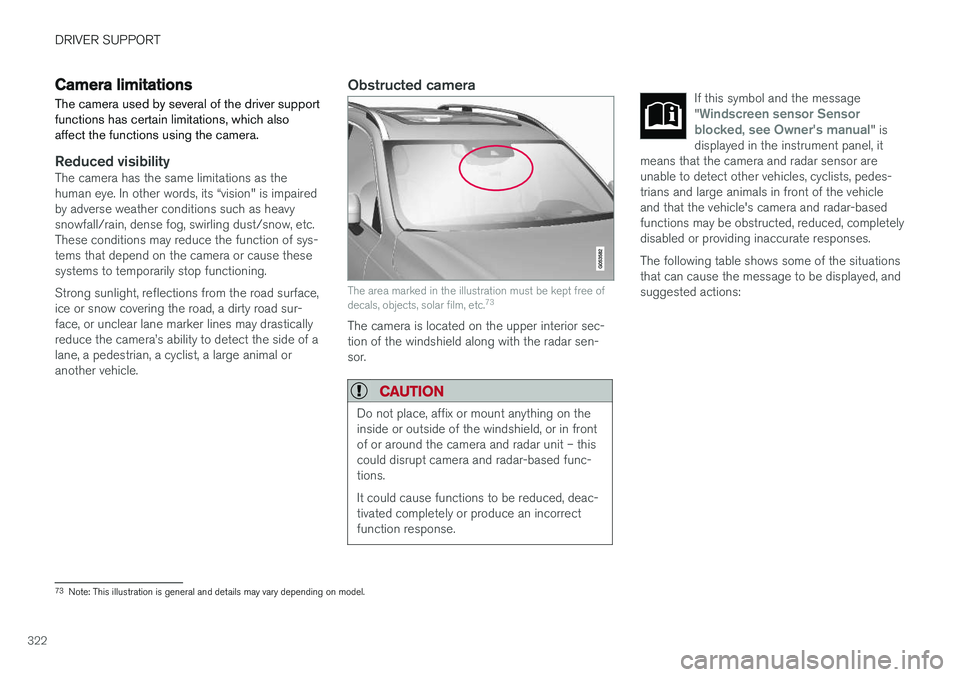
Reduced visibilityThe camera has the same limitations as the human eye. In other words, its “vision" is impairedby adverse weather conditions such as heavysnowfall/rain, dense fog, swirling dust/snow, etc.These conditions may reduce the function of sys-tems that depend on the camera or cause thesesystems to temporarily stop functioning. Strong sunlight, reflections from the road surface, ice or snow covering the road, a dirty road sur- face, or unclear lane marker lines may drastically reduce the camera
Page 325 of 674

DRIVER SUPPORT
}}}}
323
CauseAction
The area of the windshield in front of the camera/radar sensor is dirty or covered by ice or snow. Clean the windshield in front of the camera/radar sensor and remove dirt, ice andsnow.
Thick fog, heavy rain or snow is blocking the radar signals or thecamera's range of visibility. No action. Heavy precipitation may sometimes prevent the camera/radar sensor fromfunctioning.
Water or snow is spraying/swirling up and blocking the radar signalsor the camera's range of visibility. No action. Very wet or snow-covered roads may sometimes prevent the camera/radar sensor from functioning.
There is dirt between the inside of the windshield and the camera/radar sensor. Consult a workshop to have the area of the windshield on the inside of the camera'scasing cleaned. An authorized Volvo workshop is recommended.
Bright sunlight No action. The camera/radar sensor will reset automatically when lighting conditionsimprove.
NOTE
Keep the windshield in front of the camera and radar unit clean.
High temperaturesIf the temperature in the passenger compartment is very high, the camera/radar sensor will switchoff temporarily for approx. 15 minutes after theengine is started to protect its electronic compo-nents. When the temperature has cooled suffi-ciently, the camera/radar sensor will automati-cally restart.
Damaged windshield
CAUTION
If there are cracks, scratches or stone chips on the windshield in front of any of the cam-era and radar unit "windows" and this coversan area of about 0.5 × 3.0 mm(0.02 × 0.12 in.) or more, contact a workshopto have the windshield replaced – an author-ized Volvo workshop is recommended. Failure to take action could result in reduced performance for the driver support systemsthat use the camera and radar unit.
It could cause functions to be reduced, deac- tivated completely or produce an incorrectfunction response. To avoid the risk of loss of function, malfunc- tion or reduced function of the driver supportsystems that use the radar unit, the followingalso apply:
• Volvo advises
against repairing cracks,
scratches or stone chips in the area infront of the camera and radar unit – theentire windshield should instead bereplaced.
• Before replacing the windshield, contactan authorized Volvo workshop to verify
Page 467 of 674

STARTING AND DRIVING
* Option/accessory.465
Checking trailer lights
When connecting a trailer, make sure that all of the lights on the trailer are functioning beforestarting to drive.
Trailer turn signals and brake lightsIf one or more of the turn signals or brake lights on the trailer is not working, a symbol and mes-sage will be displayed in the instrument panel.The other lights on the trailer must be checkedmanually by the driver before the vehicle is driven.
SymbolMessage
•Trailer turn indicator Right
turn indicator malfunction
•Trailer turn indicator Left
turn indicator malfunction
•Trailer brake light Malfunc-
tion
If any of the trailer's turn signal lights is not work- ing, the turn signal symbol in the instrumentpanel will also flash more quickly than normal.
Trailer rear fog lightWhen a trailer is connected, the vehicle's rear foglight may not illuminate and rear fog light func-tionality is instead transferred to the trailer. If thisis the case, check to see if the trailer is equippedwith a rear fog light before activating the vehicle's fog lights when driving with a trailer to helpensure safe operation.
Checking trailer lights
*
Automatic check
When the trailer has been connected to the vehi- cle's electrical system, its lights can be checkedby automatically activating them. This functionhelps the driver check that the trailer's lights arefunctioning correctly before starting to drive. In order to perform this check, the engine must be turned off.
1. When a trailer is connected to the towbar,
the message
Automatic Trailer Lamp
Check will appear in the instrument panel.
2. Acknowledge the message by pressing the O button on the right-side steering wheel
keypad.
> The light check will begin.
3. Get out of the vehicle to perform the check. > All of the lights on the trailer will beginflashing, and then illuminate separately one at a time.
4. Visually check that all of the trailer's lights are functioning correctly.
5. After a short time, all of the trailer's lights will start flashing again.
> The light check is completed.
Disabling the automatic check
The automatic light check can be disabled in the center display. 1.Tap
Settings in the Top view.
2. Tap
My CarLights and Lighting.
3. Deselect
Automatic Trailer Lamp Check.
Manual check
If the automatic check has been disabled, the check can be started manually. 1.Tap
Settings in the Top view.
2. Tap
My CarLights and Lighting.
3. Select
Manual Trailer Lamp Check.
> The light check will begin. Get out of the vehicle to perform the check.
Related information
• Driving with a trailer (p. 462)
Page 663 of 674

INDEX
661
Electronic immobilizer 242
emergency brake lights 156
Emission inspection readiness 588Engine
automatic start and stop of combustion
engine 434
overheating 458
start 414
turn off 416
Engine braking, automatic 444 Engine compartment coolant 602
engine oil 600
overview 599
Engine drag control 264
Engine oil 600 filling 601
filter 600
grade and volume 652
Engine shutdown 416
Engine specifications 651Engine temperature high 458
Environment 27 Error messages Adaptive Cruise Control 299
see Messages and symbols 299, 314
Error messages in BLIS 343 Ethanol content
max. 10% by volume 454
Exterior dimensions 647
F
Federal Clean Air Act 588
Ferry transport 440
Flat tire 562
Flooded road 452
Fluids, volumes 640, 654
Fluids and oils 653, 654Fog lights rear 155
Four-C 440 Front seat blower 218
climate 208
heating 209, 210
temperature 218
ventilation 211
Front seat manual 180
Front seats, power 181 adjusting passenger seat from driver's
seat 187
adjusting seat 181
Lumbar support 186
massage 184, 185
memory function 182, 183
multifunction control 184, 185, 186
Side bolsters 186
FSC, environmental labeling 23
Fuel 454 Travel Link service 495
Fuel filling 453
Fuel gauge 82
Fuel requirements 454, 455 Fuel tank volume 654
Fuse box 611Fuses below the glove compartment 616
general 610
in engine compartment 612
in the cargo compartment 619
replacing 611
G
Gasoline grade 454 Gauge
fuel gauge 82