2018 VOLVO V90 CROSS COUNTRY tow bar
[x] Cancel search: tow barPage 385 of 662
DRIVER SUPPORT
}}
* Option/accessory.383
CAUTION
•Bear in mind that when the rearward camera view is selected, the screen onlyshows the area behind the vehicle – payattention to the sides and front of thevehicle when steering while reversing.
• The same applies to the reverse – payattention to what is happening with therear parts of the vehicle when the frontcamera view is selected.
• Note that the guide lines show the
short-
est path – pay extra attention to ensure
that the vehicle sides do not come incontact with/travel over anything whensteering while driving forward or that thevehicle front moves toward/over anythingwhen steering while reversing.
Trajectory lines in 360° view *
360° view with trajectory lines120
.
In the 360° view, trajectory lines are shown behind, in front of, or to the sides of the vehicle,depending on the direction of travel.
• When driving forward: Front lines
• When backing up: Side lines and rear lines.
When the front or rear camera is selected, thetrajectory lines will be shown regardless of thevehicle's direction of travel. With a side camera selected, the trajectory lines will only be shown if the vehicle is backing up.
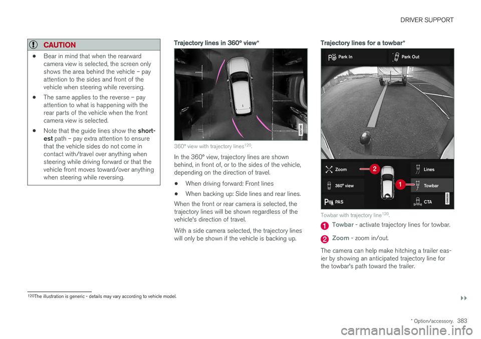
Trajectory lines for a towbar *
Towbar with trajectory line120
.
Towbar - activate trajectory lines for towbar.
Zoom - zoom in/out.
The camera can help make hitching a trailer eas- ier by showing an anticipated trajectory line for the towbar's path toward the trailer.
120 The illustration is generic - details may vary according to vehicle model.
Page 386 of 662

||
DRIVER SUPPORT
* Option/accessory.
384 1.
Tap
Towbar (1).
> The trajectory line for the towbar's antici- pated path toward the vehicle will appear and the vehicle's trajectory lines will dis-appear. Trajectory lines cannot be displayed for both the vehicle and the towbar at thesame time.
2. Tap
Zoom (2) for a close-up view for more
precise maneuvering.
> The camera will zoom in.
Related information
• Park Assist Camera
* (p. 380)
Sensor field from Park Assist forPark Assist Camera
If the vehicle is equipped with Park Assist, dis- tances will be shown in the 360° view with col-ored fields for each sensor that has detected anobstacle.
Front and rear sensors
The screen can display colored sensor fields on the vehicle symbol 121
.
The front and rear fields change colors (from yel- low to orange to red) as the vehicle moves closerto an obstacle.
Front and rear fieldcolorsDistance in meters(feet)
Yellow 0.6-1.5 (2.0-4.9)
Orange 0.4-0.6 (1.3-2.0)
Red 0-0.4 (0-1.3)
Side sensor fields
The side sensor fields will only be shown in orange.
Side field colorDistance in meters (feet)
Orange 0-0.3 (0-1.0)
Related information
• Park Assist Camera
* (p. 380)
121
The illustration is generic - details may vary according to vehicle model.
Page 445 of 662
STARTING AND DRIVING
}}
* Option/accessory.443
WARNING
•Batteries generate hydrogen gas, which is flammable and explosive.
• Do not connect the jumper cable to anypart of the fuel system or to any movingparts. Avoid touching hot manifolds.
• Battery fluid contains sulfuric acid. Do notallow battery fluid to contact eyes, skin,fabrics or painted surfaces.
• If contact occurs, flush the affected areaimmediately with water. Obtain medicalhelp immediately if eyes are affected.
• Never expose the battery to open flameor electric spark. Do not smoke near thebattery. Failure to follow the instructionsfor jump starting can lead to injury.
Related information
• Starting the vehicle (p. 400)
• Ignition modes (p. 403)
• Adjusting the steering wheel (p. 200)
• Selecting ignition mode (p. 404)
Retractable towbar
*
The Volvo retractable towbar is specially designed for the vehicle.
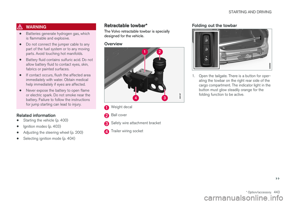
Overview
Weight decal
Ball cover
Safety wire attachment bracket
Trailer wiring socket
Folding out the towbar
1. Open the tailgate. There is a button for oper- ating the towbar on the right rear side of the cargo compartment. The indicator light in thebutton must glow steadily orange for thefolding function to be active.
Page 446 of 662
||
STARTING AND DRIVING
444
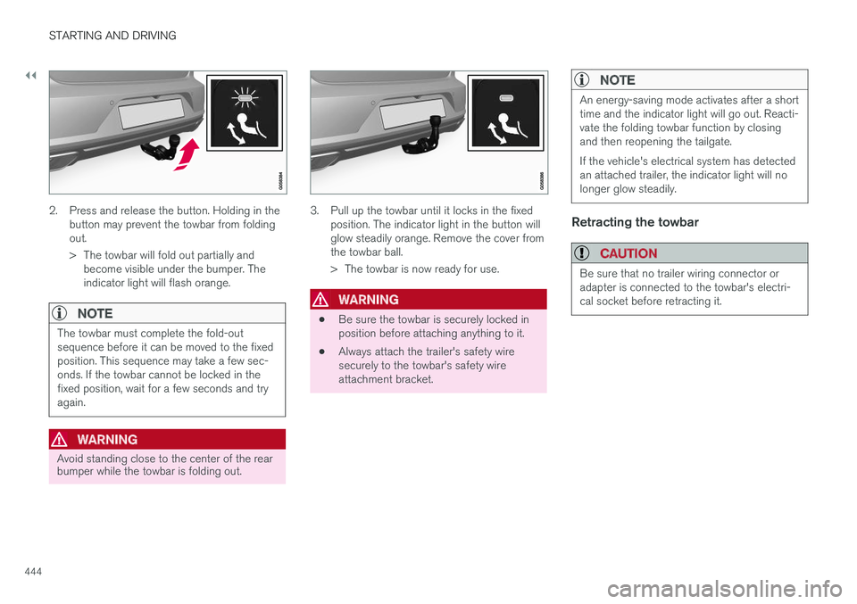
2. Press and release the button. Holding in thebutton may prevent the towbar from folding out.
> The towbar will fold out partially andbecome visible under the bumper. The indicator light will flash orange.
NOTE
The towbar must complete the fold-out sequence before it can be moved to the fixedposition. This sequence may take a few sec-onds. If the towbar cannot be locked in thefixed position, wait for a few seconds and tryagain.
WARNING
Avoid standing close to the center of the rear bumper while the towbar is folding out.
3. Pull up the towbar until it locks in the fixed position. The indicator light in the button will glow steadily orange. Remove the cover fromthe towbar ball.
> The towbar is now ready for use.
WARNING
• Be sure the towbar is securely locked in position before attaching anything to it.
• Always attach the trailer's safety wiresecurely to the towbar's safety wireattachment bracket.
NOTE
An energy-saving mode activates after a short time and the indicator light will go out. Reacti-vate the folding towbar function by closingand then reopening the tailgate. If the vehicle's electrical system has detected an attached trailer, the indicator light will nolonger glow steadily.
Retracting the towbar
CAUTION
Be sure that no trailer wiring connector or adapter is connected to the towbar's electri-cal socket before retracting it.
Page 447 of 662
STARTING AND DRIVING
}}
445
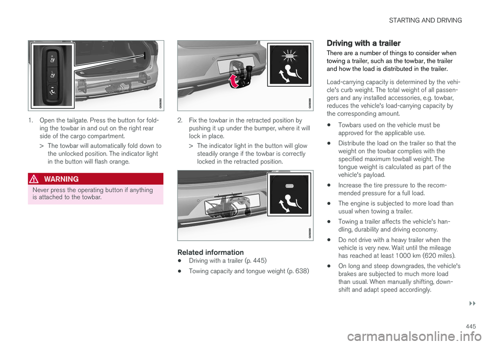
1. Open the tailgate. Press the button for fold-ing the towbar in and out on the right rear side of the cargo compartment.
> The towbar will automatically fold down tothe unlocked position. The indicator light in the button will flash orange.
WARNING
Never press the operating button if anything is attached to the towbar.
2. Fix the towbar in the retracted position by pushing it up under the bumper, where it will lock in place.
> The indicator light in the button will glowsteadily orange if the towbar is correctly locked in the retracted position.
Related information
• Driving with a trailer (p. 445)
• Towing capacity and tongue weight (p. 638)
Driving with a trailer
There are a number of things to consider when towing a trailer, such as the towbar, the trailerand how the load is distributed in the trailer.
Load-carrying capacity is determined by the vehi- cle's curb weight. The total weight of all passen-gers and any installed accessories, e.g. towbar,reduces the vehicle's load-carrying capacity bythe corresponding amount. • Towbars used on the vehicle must be approved for the applicable use.
• Distribute the load on the trailer so that theweight on the towbar complies with thespecified maximum towball weight. Thetongue weight is calculated as part of thevehicle's payload.
• Increase the tire pressure to the recom-mended pressure for a full load.
• The engine is subjected to more load thanusual when towing a trailer.
• Towing a trailer affects the vehicle's han-dling, durability and driving economy.
• Do not drive with a heavy trailer when thevehicle is very new. Wait until the mileagehas reached at least 1000 km (620 miles).
• On long and steep downgrades, the vehicle'sbrakes are subjected to much more loadthan usual. When manually shifting, down-shift and adapt speed accordingly.
Page 450 of 662

||
STARTING AND DRIVING
* Option/accessory.
448 When Trailer Stability Assist is activated, the
ESC symbol is
displayed in the instrument panel.
Related information
• Driving with a trailer (p. 445)
• Electronic Stability Control (p. 268)
Checking trailer lights
When connecting a trailer, make sure that all of the lights on the trailer are functioning beforestarting to drive.
Trailer turn signals and brake lightsIf one or more of the turn signals or brake lights on the trailer is not working, a symbol and mes-sage will be displayed in the instrument panel.The other lights on the trailer must be checkedmanually by the driver before the vehicle is driven.
SymbolMessage
•Trailer turn indicator Right
turn indicator malfunction
•Trailer turn indicator Left
turn indicator malfunction
•Trailer brake light Malfunc-
tion
If any of the trailer's turn signal lights is not work- ing, the turn signal symbol in the instrumentpanel will also flash more quickly than normal.
Trailer rear fog lightWhen a trailer is connected, the vehicle's rear foglight may not illuminate and rear fog light func-tionality is instead transferred to the trailer. If thisis the case, check to see if the trailer is equippedwith a rear fog light before activating the vehicle's fog lights when driving with a trailer to helpensure safe operation.
Checking trailer lights
*
Automatic check
When the trailer has been connected to the vehi- cle's electrical system, its lights can be checkedby automatically activating them. This functionhelps the driver check that the trailer's lights arefunctioning correctly before starting to drive. In order to perform this check, the engine must be turned off.
1. When a trailer is connected to the towbar,
the message
Automatic Trailer Lamp
Check will appear in the instrument panel.
2. Acknowledge the message by pressing the O button on the right-side steering wheel
keypad.
> The light check will begin.
3. Get out of the vehicle to perform the check. > All of the lights on the trailer will beginflashing, and then illuminate separately one at a time.
4. Visually check that all of the trailer's lights are functioning correctly.
5. After a short time, all of the trailer's lights will start flashing again.
> The light check is completed.
Page 452 of 662
||
STARTING AND DRIVING
450
CAUTION
Attempting to tow with the engine running could result in damage to the three-way cata-lytic converter.
Related information
•Attaching and removing the towing eyelet (p. 450)
• Hazard warning flashers (p. 164)
• Recovery (p. 452)
• Jump starting using another battery (p. 442)
• Selecting ignition mode (p. 404)
Attaching and removing the towingeyelet
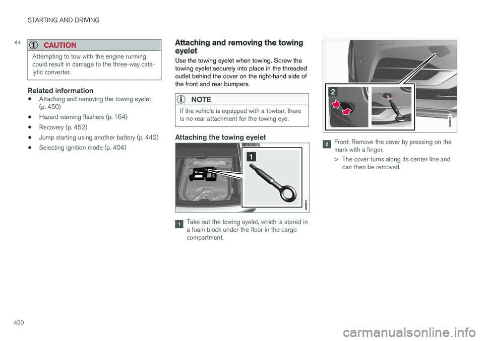
Use the towing eyelet when towing. Screw the towing eyelet securely into place in the threadedoutlet behind the cover on the right-hand side ofthe front and rear bumpers.
NOTE
If the vehicle is equipped with a towbar, there is no rear attachment for the towing eye.
Attaching the towing eyelet
Take out the towing eyelet, which is stored in a foam block under the floor in the cargocompartment.
Front: Remove the cover by pressing on the mark with a finger.
> The cover turns along its center line and can then be removed.
Page 551 of 662
WHEELS AND TIRES
}}
549
7. Connect the electrical cable to the nearest
12 V outlet and start the vehicle.
NOTE
Make sure that none of the vehicle's other 12 V sockets are used while the compressoris running.
WARNING
Never leave children unattended in the vehicle while the engine is running. 8. Start the compressor by moving the switch to
the I (On) position.
WARNING
Never stand next to a tire being inflated with the compressor. If cracks, bulges, etc. form onthe tire, switch off the compressor immedi-ately. The vehicle should not be driven. Callroadside assistance to have the vehicle towedto a workshop for inspection/replacement ofthe tire. Volvo recommends an authorizedworkshop.
NOTE
When the compressor first starts, air pressure may temporarily increase up to 6 bar (88 psi)but should decrease again after approxi-mately 30 seconds.
9. Inflate the tire for 7 minutes.
CAUTION
To help avoid overheating, the compressor should never be used for more than10 minutes at a time.
10. Switch off the compressor and check the
inflation pressure using the air pressure gauge. The inflation pressure should bebetween 1.8 bar (22 psi) and 3.5 bar(51 psi). If the inflation pressure is too high,use the air release valve to release air.
WARNING
If the bottle is not removed in the correct order, sealant could spill out.
WARNING
If pressure falls below 1.8 bar (22 psi), the hole in the tire may be too large. The vehicleshould not be driven. Call roadside assistanceto have the vehicle towed to a workshop forinspection/replacement of the tire. Volvo rec-ommends an authorized workshop.
11. Switch off the compressor and remove the electrical cable.
12. Unscrew the hose from the tire's valve and screw the valve cap back on.
13. Put the protective hose cover onto the hose to help prevent leakage of any residual seal- ing compound. Return the equipment to thecargo compartment.