2018 VOLVO V60 CROSS COUNTRY seats
[x] Cancel search: seatsPage 92 of 404

||
INSTRUMENTS AND CONTROLS
90
Release and lower the center head restraint (see Rear seats – head restraints (p. 87)) ifthe center and/or right section of the back-rest is to be lowered. The outboard headrestraints fold down automatically.
Pull up the backrest release control on the respective section(s) (
) and fold the sec-
tion(s) down. A red indicator (
) shows that
the backrest is not locked in the upright position.
NOTE
It may be necessary to move the front seats forward or put their backrests in a moreupright position before folding down the rearseat backrests.
WARNING
• When one or more sections of the back- rest is returned to the upright position,check that it is properly locked in place bypushing and pulling it. The red indicatorsshould also not be visible.
• Return the outboard head restraints tothe upright position.
• Long loads should always be securelyanchored to help avoid injury in the eventof a sudden stop.
• Always turn the engine off and apply theparking brake when loading/unloadingthe vehicle.
• Place the transmission in the Park (
P)
position to help prevent inadvertentmovement of the gear selector.
• On hot days, the temperature in the vehi-cle interior can rise very quickly. Exposureof people to these high temperatures foreven a short period of time can causeheat-related injury or death. Small chil-dren are particularly at risk.
Related information
• Front seats (p. 83)
• Front seats – power seat (p. 84)
• Rear seats – head restraints (p. 87)
Page 99 of 404

INSTRUMENTS AND CONTROLS
97
Instrument and "theater" lighting
Instrument lightingIllumination of the display and instrument lights will vary, depending on ignition mode. The display lighting is automatically subdued in darkness and the sensitivity is set with the thumbwheel. The intensity of the instrument lighting is adjusted with the thumb wheel.
"Theater" lightingWhen the overhead courtesy lighting has goneout and the engine is running, several LEDslocated near the roof console illuminate to pro-vide faint lighting for the occupants of the frontseats. This lighting goes out just after the over-head courtesy lighting when the vehicle is locked.
Related information
•Lighting panel (p. 92)
• Front interior lighting (p. 100)
• Rear interior lighting (p. 101)
• Ignition modes (p. 82)
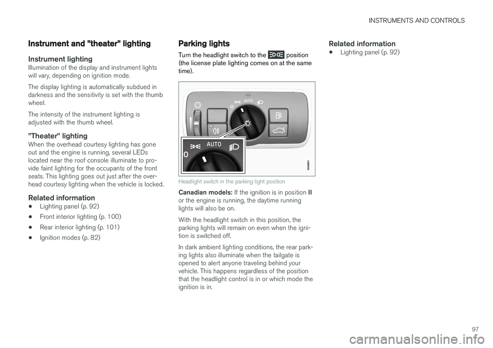
Parking lights Turn the headlight switch to the
position
(the license plate lighting comes on at the same time).
Headlight switch in the parking light position
Canadian models: If the ignition is in position II
or the engine is running, the daytime running lights will also be on. With the headlight switch in this position, the parking lights will remain on even when the igni-tion is switched off. In dark ambient lighting conditions, the rear park- ing lights also illuminate when the tailgate isopened to alert anyone traveling behind yourvehicle. This happens regardless of the positionthat the headlight control is in or which mode theignition is in.
Related information
• Lighting panel (p. 92)
Page 135 of 404

CLIMATE
* Option/accessory.133
Heated seats
The front seat heating has three levels to increase comfort for the driver and passenger incold weather. The rear outboard seat heating has three levels to increase comfort for the passengers in coldweather.
Heated front seats *
The current seat temperature setting is shown in the center console display
Press the lower section of the button repeatedly until thedesired number of indicatorlights illuminate: Highest heat level – three indi- cator lights.
Medium heat level – two indicator lights.
Lowest heat level – one indicator light. If no indicator lights are illuminated, the seat heating is switched off. Seat heating will automatically switch off when the engine is switched off.
Starting the seat heating automatically
This setting starts heating the driver's seat (at the highest level) automatically when the engine isstarted if the ambient temperature is belowapprox. 50° F (10° C). Activate/deactivate this function in the MY CAR
menu system, under
SettingsClimate
settings
Auto start driver seat heater.
Heated rear seats *
Heat control for the outboard seating positions is done in the same way as for the front seats.
Related information
•Climate – general information (p. 128)
• Electronic climate control (ECC) (p. 132)
Page 146 of 404

LOADING AND STORAGE
* Option/accessory.
144
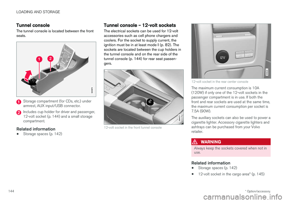
Tunnel console The tunnel console is located between the front seats.
Storage compartment (for CDs, etc.) under armrest, AUX input/USB connector.
Includes cup holder for driver and passenger, 12-volt socket (p. 144) and a small storagecompartment.
Related information
• Storage spaces (p. 142)
Tunnel console – 12-volt sockets
The electrical sockets can be used for 12-volt accessories such as cell phone chargers andcoolers. For the socket to supply current, theignition must be in at least mode I (p. 82). The
sockets are located between the cup holders inthe tunnel console and on the rear side of the
tunnel console (p. 144) for rear seat passen-gers.
12-volt socket in the front tunnel console
12-volt socket in the rear center console
The maximum current consumption is 10A (120W) if only one of the 12-volt sockets in thepassenger compartment is in use. If both thefront and rear sockets are used at the same time,the maximum current consumption per socket is7.5A (90W). The auxiliary sockets can also be used to power a cigarette lighter. Accessory cigarette lighters andashtrays can be purchased from your Volvoretailer.
WARNING
Always keep the sockets covered when not in use.
Related information
• Storage spaces (p. 142)
• 12-volt socket in the cargo area
* (p. 145)
Page 148 of 404

LOADING AND STORAGE
146
Loading – general
The load carrying capacity of your vehicle is determined by factors such as the number ofpassengers, the amount of cargo, the weight ofany accessories that may be installed, etc.
To increase loading space, the rear seat back- rests can be folded down, see Rear seats – fold-
ing backrest (p. 89).
When loading the cargo area, keep the following
in mind:
• Load objects in the cargo area against thebackrest whenever possible.
• Unstable loads can be secured to the loadanchoring eyelets with straps or web lash-ings to help keep them from shifting.
• Stop the engine and apply the parking brakewhen loading or unloading long objects. Thegear selector can be knocked out of positionby long loads, which could set the vehicle inmotion.
WARNING
• Stop the engine, put the gear selector in P
, and apply the parking brake when
loading or unloading long objects.
• The vehicle's driving characteristics may change depending on the weight and dis-tribution of the load.
• A 44-pound (20 kg) object produces aforce of 2,200 pounds (1,000 kg) in ahead-on collision at 30 mph (50 km/h).
• The cargo compartment and rear seatshould not be loaded to a level higherthan 2 in. (5 cm) below the upper edge ofthe rear side windows. Objects placedhigher than this level could impede thefunction of the Inflatable Curtain.
Related information
• Load anchoring eyelets (p. 147)
• Steel cargo grid (p. 150)
• Loading – roof load carriers (p. 146)
Loading – roof load carriers
Using load carriersLoad carriers are available as Volvo accessories. Observe the following points when in use:
• To avoid damaging your vehicle and toachieve maximum safety when driving, werecommend using the load carriers that Volvohas developed especially for your vehicle.
• Volvo-approved removable roof racks aredesigned to carry the maximum allowableroof load for this vehicle: 220 lbs (100 kg).For non-Volvo roof racks, check the manu-facturer's weight limits for the rack.
• Never exceed the rack manufacturer's weighlimits and never exceed the maximum ratedroof load of 220 lbs (100 kg).
• Avoid single-point loads. Distribute loadsevenly.
• Place heavier cargo at the bottom of theload.
• Secure the cargo correctly with appropriatetie-down equipment.
• Check periodically that the load carriers andload are properly secured.
• Remember that the vehicle's center of gravityand handling change when you carry a loadon the roof.
Page 150 of 404

LOADING AND STORAGE
148
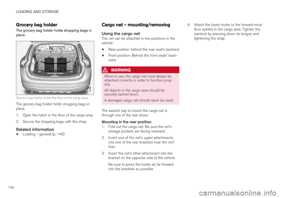
Grocery bag holder
The grocery bag holder holds shopping bags in place.
Grocery bag holder under the floor of the cargo area
The grocery bag holder holds shopping bags in place.
1. Open the hatch in the floor of the cargo area.
2. Secure the shopping bags with the strap.
Related information
• Loading – general (p. 146)
Cargo net – mounting/removing
Using the cargo netThe net can be attached in two positions in the vehicle:
• Rear position: behind the rear seat's backrest
• Front position: Behind the front seats' back-rests
WARNING
When in use, the cargo net must always be attached correctly in order to function prop-erly. All objects in the cargo area should be securely lashed down. A damaged cargo net should never be used.
The easiest way to mount the cargo net is through one of the rear doors.
Mounting in the rear position
1. Fold out the cargo net. Be sure the net's storage pockets are facing rearward.
2. Insert one of the net's upper attachments into one of the rear brackets near the roof liner.
3. Insert the net's other attachment into the bracket on the opposite side of the vehicle. Be sure to press the hooks as far forward into the brackets as possible. 4. Attach the lower hooks to the forward-most
floor eyelets in the cargo area. Tighten thecamlock by pressing down its tongue andtightening the strap.
Page 151 of 404

LOADING AND STORAGE
}}
149
Mounting in the front position
1. Fold out the cargo net. Be sure the net'sstorage pockets are facing rearward.
2. Attaching the net is easier if the front seats are moved as far forward as possible.
3. Insert one of the net's upper attachments into one of the front brackets near the roof liner.
4. Insert the net's other attachment into the bracket on the opposite side of the vehicle. Be sure to press the hooks as far forward into the brackets as possible.
5. Attach the lower hooks to the eyelets on the front seat floor rails. Tighten the camlock bypressing down its tongue and tightening thestrap.
If the front seats are moved rearward, they shouldnot press hard against the net.
CAUTION
When moving the front seats with the cargo net installed, only move the seat(s)/back-rest(s) rearward until they touch the net. Excessive pressure from the front seats against the cargo net could damage the netand/or its brackets.
Removing and storing the cargo net
1. Release the lower hooks.
2. Remove the net's upper attachments from the ceiling brackets.
3. Fold the net.When not in use, the cargo net can be stored under floor of the cargo area.
Related information
• Loading – general (p. 146)
• Steel cargo grid (p. 150)
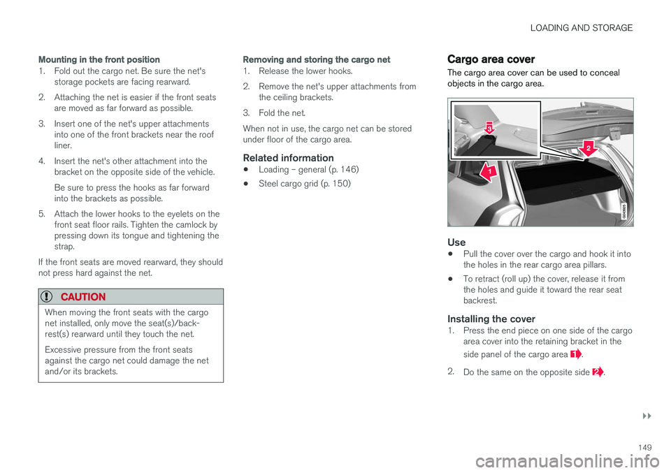
Cargo area cover
The cargo area cover can be used to conceal objects in the cargo area.
Use
• Pull the cover over the cargo and hook it into the holes in the rear cargo area pillars.
• To retract (roll up) the cover, release it fromthe holes and guide it toward the rear seatbackrest.
Installing the cover1. Press the end piece on one side of the cargo
area cover into the retaining bracket in the side panel of the cargo area
.
2. Do the same on the opposite side
.
Page 155 of 404

LOCKS AND ALARM
* Option/accessory.153
Related information
•Remote key – functions (p. 155)
Key memory
The memory in the remote key makes it possible to store certain personal settings.
The position of the side door mirrors, power driv- er's seat * and the selected instrument panel
theme 1
are stored in the remote keys when the
vehicle is locked . The next time the driver's door
is unlocked with the same remote key and the
door is opened within 2 minutes, the power driv-
er's seat and side door mirrors will automatically move to the position that they were in when thedoors were most recently locked with the sameremote key. If the seat/mirrors have not beenreadjusted since the vehicle was locked, they willalready be in the position stored in that particularremote key and will not move. For more informa-tion on this feature, see Front seats – power seat(p. 84). This feature can be activated or deactivated in the vehicle's menu by pressing MY CAR and
going into
SettingsCar settingsCar key
memory. For a description of the menu system,
see My Car – introduction (p. 79).
NOTE
If the vehicle is locked with the remote key or is left unlocked for more than 30 minutes, thekey memory function will be deactivated. To reactivate the key's memory:
• Press the unlock button on the remote key.
For information regarding vehicles with the optional keyless drive, see Keyless drive
*– lock-
ing/unlocking (p. 161).
Related information
• Locking/unlocking confirmation (p. 154)
1
Optional digital instrument panel only