Page 348 of 404
||
MAINTENANCE AND SERVICING
3462. Reinstall the headlight housing and locking
pins. The short locking pin should be closest to the grille. Check that they are correctlyinserted. The headlight housing must be properly in place and the wiring connector correctlyreconnected before the lighting is switchedon or the remote key is inserted into the igni-tion slot.
3. Check that the lights function properly.
Related information
• Bulbs – introduction (p. 344)
• Bulbs – cover (p. 346)
• Bulbs – specifications (p. 351)
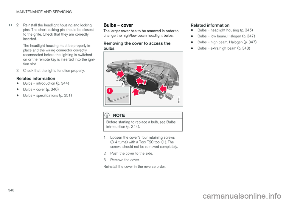
Bulbs – cover The larger cover has to be removed in order to change the high/low beam headlight bulbs.
Removing the cover to access the
bulbs
NOTE
Before starting to replace a bulb, see Bulbs – introduction (p. 344).
1. Loosen the cover's four retaining screws (3-4 turns) with a Torx T20 tool (1). The screws should not be removed completely.
2. Push the cover to the side.
3. Remove the cover.Reinstall the cover in the reverse order.
Related information
• Bulbs – headlight housing (p. 345)
• Bulbs – low beam, Halogen (p. 347)
• Bulbs – high beam, Halogen (p. 347)
• Bulbs – extra high beam (p. 348)
Page 349 of 404
MAINTENANCE AND SERVICING
347
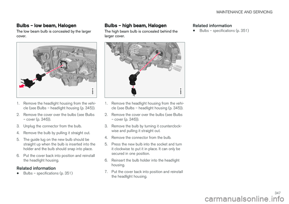
Bulbs – low beam, Halogen The low beam bulb is concealed by the larger cover.
1. Remove the headlight housing from the vehi-cle (see Bulbs – headlight housing (p. 345)).
2. Remove the cover over the bulbs (see Bulbs – cover (p. 346)).
3. Unplug the connector from the bulb.
4. Remove the bulb by pulling it straight out.
5. The guide lug on the new bulb should be straight up when the bulb is inserted into the holder and the bulb should snap into place.
6. Put the cover back into position and reinstall the headlight housing.
Related information
• Bulbs – specifications (p. 351)
Bulbs – high beam, Halogen
The high beam bulb is concealed behind the larger cover.
1. Remove the headlight housing from the vehi- cle (see Bulbs – headlight housing (p. 345)).
2. Remove the cover over the bulbs (see Bulbs – cover (p. 346)).
3. Remove the bulb by turning it counterclock- wise and pulling it straight out.
4. Remove the connector from the bulb.
5. Press the new bulb into the socket and turn it clockwise to put it in place. It can only be secured in one position.
6. Reinsert the bulb holder into the headlight housing.
7. Put the cover back into position and reinstall the headlight housing.
Related information
• Bulbs – specifications (p. 351)
Page 350 of 404
MAINTENANCE AND SERVICING
348
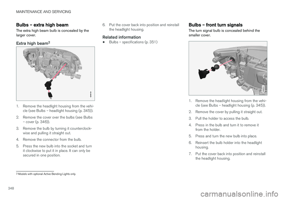
Bulbs – extra high beam The extra high beam bulb is concealed by the larger cover.
Extra high beam2
1. Remove the headlight housing from the vehi-
cle (see Bulbs – headlight housing (p. 345)).
2. Remove the cover over the bulbs (see Bulbs – cover (p. 346)).
3. Remove the bulb by turning it counterclock- wise and pulling it straight out.
4. Remove the connector from the bulb.
5. Press the new bulb into the socket and turn it clockwise to put it in place. It can only be secured in one position. 6. Put the cover back into position and reinstall
the headlight housing.
Related information
• Bulbs – specifications (p. 351)
Bulbs – front turn signals The turn signal bulb is concealed behind the smaller cover.
1. Remove the headlight housing from the vehi-
cle (see Bulbs – headlight housing (p. 345)).
2. Remove the cover by pulling it straight out.
3. Pull the holder to access the bulb.
4. Press in the bulb and turn it to remove it from the holder.
5. Press and turn the new bulb into place.
6. Reinsert the bulb holder into the headlight housing.
7. Put the cover back into position and reinstall the headlight housing.
2Models with optional Active Bending Lights only.
Page 351 of 404
MAINTENANCE AND SERVICING
349
Related information
•Bulbs – specifications (p. 351)
Bulbs – taillight housing The backup lights, fog lights and turn signals are replaced from inside the cargo area
Brake light (LED)
Parking lights/side marker light (LED)
Turn signal
Brake light (LED)
Backup light
Rear fog light
1. Open the panel.
2. Pull the insulation in front of the bulb holder
straight out.
3. Press down the catch and pull out the bulb holder.
4. Remove the defective bulb by pressing it in and turning it counterclockwise.
5. Press a new bulb into place and turn it clock- wise.
6. Hold down the catch and press the bulb holder back into place.
7. Put the insulation and panel back in place.
Related information
• Bulbs – introduction (p. 344)
• Bulbs – specifications (p. 351)
Page 352 of 404
MAINTENANCE AND SERVICING
350
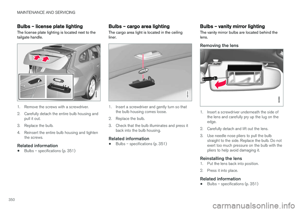
Bulbs – license plate lightingThe license plate lighting is located next to the tailgate handle.
1. Remove the screws with a screwdriver.
2. Carefully detach the entire bulb housing and pull it out.
3. Replace the bulb.
4. Reinsert the entire bulb housing and tighten the screws.
Related information
• Bulbs – specifications (p. 351)
Bulbs – cargo area lighting
The cargo area light is located in the ceiling liner.
G031942
1. Insert a screwdriver and gently turn so that the bulb housing comes loose.
2. Replace the bulb.
3. Check that the bulb illuminates and press it back into the bulb housing.
Related information
• Bulbs – specifications (p. 351)
Bulbs – vanity mirror lighting
The vanity mirror bulbs are located behind the lens.
Removing the lens
1. Insert a screwdriver underneath the side of the lens and carefully pry up the lug on the edge.
2. Carefully detach and lift out the lens.
3. Use needle nose pliers to pull the bulb straight to the side. Replace the bulb. Do not exert too much pressure on the bulb with thepliers to help avoid damaging it.
Reinstalling the lens1. Put the lens back into position.
2. Press it into place.
Related information
• Bulbs – specifications (p. 351)
Page 353 of 404
MAINTENANCE AND SERVICING
}}
* Option/accessory.351
Bulbs – specifications The following bulbs can be replaced by the vehi- cles owner. All other bulbs should only bereplaced by a trained and qualified Volvo servicetechnician.
Lighting function Wat-
tage Bulb
Low beam (halo- gen) 55 H11 LL
High beam (halo-gen) 65 H9
Extra high beam(models withActive Bending Lights *) 55 H7 LL
Front turn signals 24 PY24W License plate light- ing 5 C5W LL
Vanity mirror light-ing 1.2 W2x4.6d type
T5
Glove compart-ment lighting 5 SV8.5 (length
43mm)
Rear turn signals 21 PY21W LL
Rear fog light 21 H21W LL
Lighting function Wat-
tage Bulb
Backup light 21 H21W LL
Brake light 21 P21W LL
Cargo area lighting 5 SV8.5 (length 43mm)
Front footwell lighting 3 W2, 1x9.5d
type T10
NOTE
Please consult a Volvo retailer
Page 354 of 404

||
MAINTENANCE AND SERVICING
352To put the windshiield wipers in the service posi- tion: 1.
Insert the remote key into the ignition slot 3
and press the START/STOP ENGINE but-
ton briefly to put the ignition in mode I (see
Ignition modes (p. 82) for detailed informa- tion about the ignition modes).
2. Press the START/STOP ENGINE button
again briefly to switch the ignition off.
3. Within 3 seconds, move the right steering wheel lever up and hold it for at least 1 sec-ond.
> The wipers will then move to the vertical(service) position on the windshield.
The wipers can be returned to the normal posi- tion by pressing the START/STOP ENGINE but-
ton briefly to put the ignition in mode I (or by
starting the engine).
CAUTION
If the wiper arms have been folded out from the windshield while in the service position,fold them back against the windshield beforereturning the wipers to the normal position tohelp avoid scratching the paint on the hood.
Related information
• Engine compartment – washer fluid (p. 354)
Wiper blades – windshield The wiper blades should be replaced regularly for best effect. The windshield wiper blades must be in the verti- cal (service) position for replacement, washingor to lift them away from the windshield whene.g., removing ice or snow.
Replacing the windshield wiper blades
NOTE
The windshield wiper blades are different lengths. The blade on the driver
Page 355 of 404
MAINTENANCE AND SERVICING
353
With the wipers in the service position, fold out the wiper arm from the windshield. Pressthe button on the wiper blade attachmentand pull the wiper blade straight out, parallelwith the wiper arm.
Slide in the new wiper blade until it clicks into place.
Check that the blade is securely in place.
4. Press the wipers back against the wind- shield.
To return the wipers from the service position to the normal position, fold the wipers back against the windshield and press the START/STOP
ENGINE button briefly to put the ignition in mode
I (or start the engine).
CleaningKeeping the windshield and wiper blades clean helps improve visibility and prolongs the servicelife of the wiper blades. Clean the wiper bladeswith a stiff-bristle brush and lukewarm soap solu-tion or car washing detergent.
Related information
• Engine compartment – washer fluid (p. 354)
• Wiper blades – service position (p. 351)
Wiper blades – tailgate
The wiper blades should be replaced regularly for best effect.
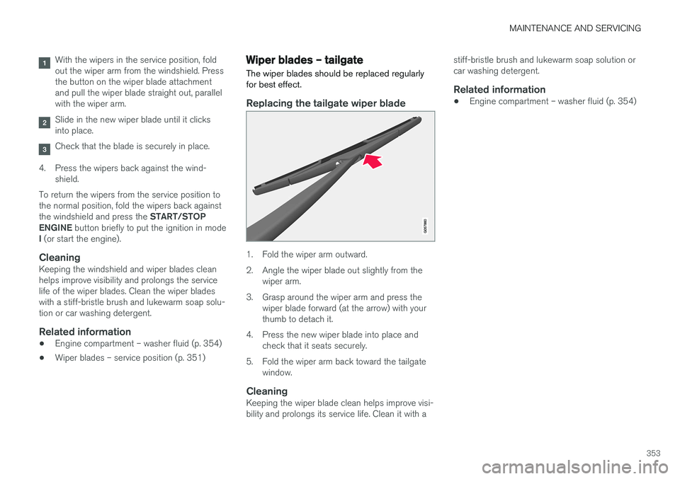
Replacing the tailgate wiper blade
1. Fold the wiper arm outward.
2. Angle the wiper blade out slightly from the wiper arm.
3. Grasp around the wiper arm and press the wiper blade forward (at the arrow) with your thumb to detach it.
4. Press the new wiper blade into place and check that it seats securely.
5. Fold the wiper arm back toward the tailgate window.
CleaningKeeping the wiper blade clean helps improve visi-bility and prolongs its service life. Clean it with a stiff-bristle brush and lukewarm soap solution orcar washing detergent.
Related information
•
Engine compartment – washer fluid (p. 354)