2018 VOLVO V60 CROSS COUNTRY change time
[x] Cancel search: change timePage 211 of 404
DRIVER SUPPORT
}}
209
•
City Safety – operation (p. 204)
• City Safety – limitations (p. 204)
• City Safety – troubleshooting (p. 205)
• City Safety – symbols and messages (p. 207)
Collision warning – introduction Pedestrian and Cyclist Detection with Full Auto Brake is designed to assist the driver if there is arisk of a collision with a pedestrian, a cyclist, avehicle ahead that is at a standstill or one that ismoving in the same direction as your vehicle.
This system consists of the following three func- tions:
• Collision Warning
warns the driver of a
potential collision situation.
• Brake Support
helps the driver brake effi-
ciently in a critical situation.
• Auto-brake
brakes the vehicle automatically
if a collision with a pedestrian, a cyclist oranother vehicle cannot be avoided and thedriver does not apply the brakes in time orsteer around the person/vehicle. Auto-brakecan help prevent a collision or reduce thespeed at which a collision occurs.
Since Pedestrian and Cyclist Detection with FullAuto Brake is activated in circumstances wherethe driver should have begun braking muchsooner, the system will not be able to assist thedriver in all situations. This system is designed to activate as late as possible to help avoid unnecessary intervention. The system should not be used in such a way that the driver changes his/her way of operatingthe vehicle. If the driver relies entirely on the sys- tem, the chances of an accident eventually occur-ring increase considerably. The Pedestrian and Cyclist Detection with Full Auto Brake and City Safety
™ systems supple-
ment each other. See City Safety – introduction (p. 202) for detailed information about City Safety ™.
WARNING
No automatic system can be guaranteed to function 100% correctly in all situations. Forthat reason, never test the Auto-brake systemby driving toward a person or object. Thiscould result in serious injury or death.
Page 267 of 404
STARTING AND DRIVING
}}
* Option/accessory.265
Transmission – Geartronic
Geartronic allows you to manually shift among your vehicle's forward gears. The manual posi-tion ( +S–) can be selected at any time.
Geartronic: manual shifting (+S–)To shift gears manually, move the gear selector to the side from D toward
+S– . The +S– symbol in the instrument
panel will change from white to
orange and the number of the gear currently
being used (
1, 2, 3, etc.) will be displayed (see
the following illustration) 5
.
• To return to automatic shifting mode from +S–
, move the gear selector to the side
toward D.
Gear shift indicator *
Gear shift indicator in a digital instrument panel *6
This option indicates when to shift up or down to help conserve fuel. A white arrow will appearabove or below the number of the current gear toprompt the driver to shift up or down.
While driving
•
If you select the manual shifting position while driving, the gear that was being used inthe Drive position will also initially beselected in the manual shifting position.
• Move the gear selector forward (toward
+) to
shift to a higher gear or rearward (toward –)
to shift to a lower gear.
• If you hold the gear selector toward "
–", the
transmission will downshift one gear at atime and will utilize the braking power of the engine. If the current speed is too high forusing a lower gear, the downshift will notoccur until the speed has decreased enoughto allow the lower gear to be used.
• If you slow to a very low speed, the transmis-sion will automatically shift down.
Shiftlock: Neutral (N)
If the gear selector is in the
N position and the
vehicle has been stationary for at least 3 seconds (irrespective of whether the engine is running)then the gear selector is locked. In order to move the gear selector from N to
another gear position, the brake pedal must be depressed and the ignition must be in at least position II, see Ignition modes (p. 82).
5
If Sport mode is being used, the symbol will change to "S".
6 Analog instrument panel: the gear shift indicator is displayed in the center of the speedometer.
Page 269 of 404
STARTING AND DRIVING
}}
267
Geartronic: Sport mode ( S)7
This transmission mode provides sportier shifting characteristics and enables a more active drivingstyle by making it possible to drive at higher rpmin each gear before shifting up. The engine alsoresponds faster when the accelerator pedal ispressed. To access Sport mode from Drive (
D), move the
gear selector to the left. The transmission will not switch to manual shifting mode until the gearselector is moved forward or rearward toward +or –. Sport mode can be selected any time.
NOTE
• On vehicles equipped with Sport mode, the transmission symbol in the main instrument panel will change from
D to S
when the gear selector is moved to the manual shifting mode. If the gear selectoris moved toward "+" or "-", the number ofthe gear currently being used will be dis-played, see Information displays – intro-duction (p. 71).
• Please be aware that using Sport modemay result in a slight decrease in fuel economy. Driving in
D can help improve
fuel economy.
Geartronic : starting on slippery surfaces
Selecting 3rd gear in Geartronic
Page 275 of 404
STARTING AND DRIVING
}}
* Option/accessory.273
ECO*
Eco is a function 10
developed by Volvo to give
the driver the opportunity to actively drive more economically and to help reduce fuel consump-tion.
IntroductionWhen Eco is activated, the fol- lowing functions are modified:
• The automatic transmission's shifting points
• The engine management system and accel- erator pedal response
• Stop/stop function (Start/Stop – introduction(p. 268)): the engine can auto-stop beforethe vehicle has come to a full stop
• Eco Coast functionality is activated: enginebraking is disabled
• Climate system settings: certain functions(e.g., air conditioning) will be temporarilyreduced or deactivated
NOTE
When Eco is activated, several climate system parameters are changed and the function ofcertain current-consuming systems will bereduced. Some of these functions can be restarted manually but full functionality will not berestored until Eco is deactivated.
Function
ECO On/Off button in the center console
ECO symbol in the instrument panel
When the engine is switched off, ECO is deacti- vated and must be reactivated each time theengine is started (with the exception of certainengines). The
ECO symbol will be displayed in the instru-
ment panel and the indicator light in the ECO
button will be on when Eco is activated.
Eco on or offWhen ECO is deactivated, theECO symbol will not be dis-
played in the instrument panel and the indicator light in the ECO button will be off. The
function will remain deactivated until the button is pressedagain.
Eco CoastEco Coast is an integral part of the Eco function and essentially deactivates engine braking, allow-ing the vehicle to roll freely.
NOTE
To function optimally, Eco Coast should pri- marily be used when the vehicle can coast asfar as possible.
When the driver releases the accelerator pedal, the transmission is automatically disengagedfrom the engine and engine rpm will be reducedto the idle level (approx. 700-800 rpm), whichhelps reduce fuel consumption.
10 Option on models equipped with certain 4-cylinder engines
Page 320 of 404
||
WHEELS AND TIRES
318
NOTE
The system indicates low tire pressure but does not replace normal tire maintenance. Forinformation on correct tire pressure, pleaserefer to the tire inflation decal on the driver'sdoor opening or consult your Volvo retailer.
Related information
•Tire pressure monitoring - overview (p. 316)
• Calibrating Tire Monitor (p. 318)
Calibrating Tire Monitor In order for Tire Monitor to work correctly, tire pressure reference values must be set (the sys-tem must be calibrated). This must be doneeach time wheels or tire pressures are changed.
Calibration1. Switch off the engine.
2. Inflate the tires to the desired pressure (con-
sult tire pressure placard located on the driv- er's side B-pillar (the structural member atthe side of the vehicle).
3. Start the engine but keep the vehicle at a standstill.
4. Press the MY CAR button on the center
console control panel and press OK/MENU.
5. Select
Tire monitor.
6. Select
Start calibration and press OK/
MENU .
7. Press OK/MENU again after all of the tires
have been checked and reinflated. 8. Drive away.
> The calibration process will begin whenthe vehicle reaches a speed of approxi- mately 22 mph (35 km/h). Calibration willbe interrupted if the engine is switchedoff but will resume automatically in thebackground when the vehicle is drivenagain. The system will not give any confir-mation when calibration is finished.
When driving with heavy loads or at sustainedhighway speeds, the tire pressure should beadjusted to the recommended inflation pressuresaccording to the tire inflation pressure placardlocated on the driver's side B-pillar (the structuralmember at the side of the vehicle, at the rear ofthe driver's door opening) or to the tire inflationpressure table in the owner's information. After adjusting inflation pressure, repeat steps 1-5 above.
NOTE
Always remember to calibrate Tire Monitor when the wheels have been changed or thetire pressure has been corrected according totire pressure placard or tire pressure table. Ifcorrect reference values have not been set,the system cannot issue low tire pressurealerts correctly.
Page 323 of 404

WHEELS AND TIRES
321
Tire Pressure Monitoring System (TPMS) – changing wheels
Please keep the following in mind when chang- ing or replacing the factory installed TPMSwheels/tires on the vehicle:
• Not all aftermarket wheels are equipped withTPMS sensors in the valves.
• If the vehicle is equipped with a temporaryspare tire, this tire does not have a TPMSsensor.
• If wheels without TPMS sensors are moun-ted on the vehicle, a text message will dis-played in the instrument panel each time thevehicle is driven above 20 mph (30 km/h) for10 minutes or more.
• Once TPMS sensors are properly installed,the warning message should not reappear. Ifthe message is still displayed, drive the vehi-cle for several minutes at a speed of 20 mph(30 km/h) or faster to erase the message.
• Volvo recommends that TPMS sensors befitted on all wheels used on the vehicle,including winter tires. Volvo does not recom-mend moving sensors back and forthbetween sets of wheels.
CAUTION
When inflating tires, press the pump's mouth- piece straight onto the valve to help avoidbending or otherwise damaging the valve.
CAUTION
•After inflating the tires, always reinstall the valve cap to help avoid damage to thevalve from dirt, gravel, etc.
• Use plastic valve caps only. Metal capscould corrode and become difficult toremove.
NOTE
•
If you change to tires with a different dimension than the factory-installed ones,the TPMS system must be reconfiguredfor these tires. This must be done by atrained and qualified Volvo service techni-cian.
• If a tire is changed, or if the TPMS sensoris moved to another wheel, the sensor'sseal, nut, and valve core should bereplaced.
• When installing TPMS sensors, the vehi-cle must be parked for at least15 minutes with the ignition off. If thevehicle is driven within 15 minutes, aTPMS error message will be displayed.
Related information
• Tire Pressure Monitoring System (TPMS) – general information (p. 320)
• Tire Pressure Monitoring System (TPMS) –recalibrating (p. 322)
• Tire Pressure Monitoring System (TPMS) –messages (p. 323)
• Tire Pressure Monitoring System (TPMS) –activating/deactivating (p. 322)
Page 337 of 404

MAINTENANCE AND SERVICING
}}
* Option/accessory.335
Onboard Diagnostic System OBD II is part of your vehicle's computerized engine management system. It stores diagnosticinformation about your vehicle's emission con-trols. It can light the Check Engine light (MIL) if itdetects an emission control "fault." A "fault" is acomponent or system that is not performingwithin an expected range. A fault may be perma-nent or temporary. OBD II will store a messageabout any fault.
Emission inspection readiness
How do states use OBD II for emission inspections?
Many states connect a computer directly to a vehicle's OBD II system. The inspector can thenread "faults." In some states, this type of inspec-tion has replaced the tailpipe emission test.
How can my vehicle fail OBD II emission inspection?
Your vehicle can fail OBD II emission inspection for any of the following reasons.
• If your Check Engine (MIL) light is lit, yourvehicle may fail inspection.
• If your vehicle's Check Engine light was lit,but went out without any action on your part,OBD II will still have a recorded fault. Yourvehicle may pass or fail, depending on theinspection practices in your area.
• If you had recent service that required dis-connecting the battery, OBD II diagnostic information may be incomplete and "notready" for inspection. A vehicle that is notready may fail inspection.
How can I prepare for my next OBD II
emission inspection?
• If your Check Engine (MIL) light is lit – or was lit but went out without service, have yourvehicle diagnosed and, if necessary, servicedby a qualified Volvo technician.
• If you recently had service for a lit CheckEngine light, or if you had service thatrequired disconnecting the battery, a periodof driving is necessary to bring the OBD IIsystem to "ready" for inspection. Two half-hour trips of mixed stop-and-go/highwaydriving are typically needed to allow OBD II toreach readiness. Your Volvo retailer can pro-vide you with more information on planning atrip.
• Maintain your vehicle in accordance with yourvehicle's maintenance schedule.
Booking service and repairs
Connected Service Booking (CSB) makes set- ting up a time for service, maintenance and/orrepairs directly from the vehicle quick and con-venient.
Prerequisites
• The owner (primary driver) must have a valid Volvo ID. See Volvo ID (p. 22) for additionalinformation.
• The vehicle must be connected to the Inter- net using a paired Bluetooth ®
cell phone.
See your Sensus Infotainment supplement for information on pairing a cell phone. On models equipped with Volvo On Call (VOC) *,
you can connect to the Internet using your separate VOC data plan. Refer to your sepa-rate Volvo On Call manual.
• By default, the retailer where you purchasedyour vehicle will be your preferred (primary)retailer/Volvo authorized workshop who willperform service and repairs on your vehicle.To change the preferred retailer, go to DealerLocator at volvocars.com and select aretailer, click on Service Scheduler and bookan appointment at the new preferred retailer.
• In order to be guided through the on-screen steps, the menu alternative
Display
notifications must be activated.
Page 343 of 404
MAINTENANCE AND SERVICING
* Option/accessory.341
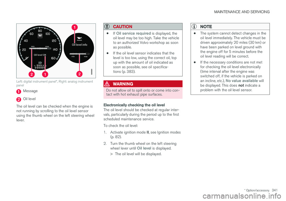
Left: digital instrument panel *, Right: analog instrument
panel
Message
Oil level
The oil level can be checked when the engine is not running by scrolling to the oil level sensorusing the thumb wheel on the left steering wheellever.
CAUTION
• If Oil service required is displayed, the
oil level may be too high. Take the vehicle to an authorized Volvo workshop as soonas possible.
• If the oil level sensor indicates that thelevel is too low, using the correct oil, topup with the amount of oil indicated assoon as possible, see oil specifica-tions (p. 383).
WARNING
Do not allow oil to spill onto or come into con- tact with hot exhaust pipe surfaces.
Electronically checking the oil level
The oil level should be checked at regular inter- vals, particularly during the period up to the firstscheduled maintenance service. To check the oil level:1.
Activate ignition mode II, see Ignition modes
(p. 82).
2. Turn the thumb wheel on the left steering wheel lever until
Oil level is displayed.
> The oil level will be displayed.
NOTE
• The system cannot detect changes in the oil level immediately. The vehicle must bedriven approximately 20 miles (30 km) orhave been parked on level ground withthe engine off for 5 minutes before theoil level reading will be correct.
• If the necessary conditions are not metfor checking the oil level electronically(time interval after the engine wasswitched off, if the vehicle is parked on an incline, etc.),
No value available will
be displayed. This does not indicate a
problem with the oil level sensor.