2018 VOLVO V60 CROSS COUNTRY roof
[x] Cancel search: roofPage 114 of 404
||
INSTRUMENTS AND CONTROLS
* Option/accessory.
112
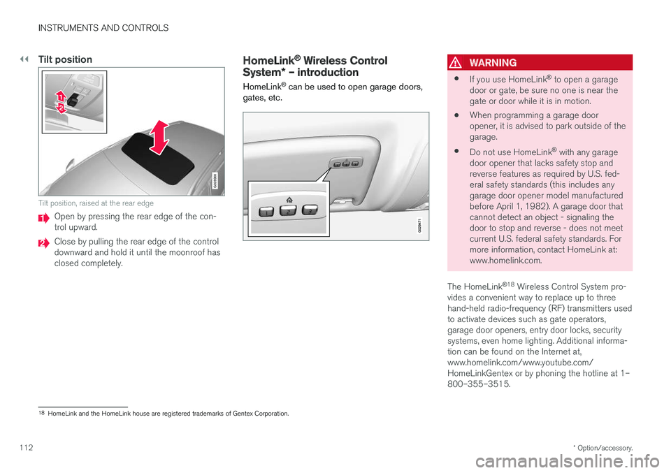
Tilt position
G028900
Tilt position, raised at the rear edge
Open by pressing the rear edge of the con- trol upward.
Close by pulling the rear edge of the control downward and hold it until the moonroof hasclosed completely.
HomeLink ®
Wireless Control
System * – introduction
HomeLink ®
can be used to open garage doors,
gates, etc.WARNING
• If you use HomeLink ®
to open a garage
door or gate, be sure no one is near the gate or door while it is in motion.
• When programming a garage dooropener, it is advised to park outside of thegarage.
• Do not use HomeLink ®
with any garage
door opener that lacks safety stop andreverse features as required by U.S. fed-eral safety standards (this includes anygarage door opener model manufacturedbefore April 1, 1982). A garage door thatcannot detect an object - signaling thedoor to stop and reverse - does not meetcurrent U.S. federal safety standards. Formore information, contact HomeLink at:www.homelink.com.
The HomeLink ®
18
Wireless Control System pro-
vides a convenient way to replace up to threehand-held radio-frequency (RF) transmitters usedto activate devices such as gate operators,garage door openers, entry door locks, securitysystems, even home lighting. Additional informa-tion can be found on the Internet at,www.homelink.com/www.youtube.com/HomeLinkGentex or by phoning the hotline at 1–800–355–3515.
18 HomeLink and the HomeLink house are registered trademarks of Gentex Corporation.
Page 130 of 404
CLIMATE
* Option/accessory.
128
Climate – general information
The vehicle is equipped with Electronic Climate
Control (ECC) (p. 132) that cools, heats or dehumidifies the air in the passenger compart-ment.
Air conditioning
NOTE
• The air conditioning can be switched off, but to ensure the best possible climatecomfort in the passenger compartmentand to prevent the windows from misting,it should always be on.
• In warm weather, a small amount of watermay accumulate under the car when ithas been parked. This water is condensa-tion from the A/C system and is normal.
Side windows and moonroofTo ensure that the air conditioning works opti- mally, the side windows, and the optional moon-roof should be closed.
Fog on the inside of the windowsThe defroster function (p. 135) should be usedto remove fog or mist from the inside of the win-dows. Keeping the windows clean with a com-mercially available window washing spray will alsohelp prevent fogging or misting.
Temporary shut-off of the air conditioning
The air conditioning (p. 135) is momentarily dis- engaged during full acceleration or when drivinguphill with a trailer. This may result in a temporaryincrease in cabin temperature.
Ice and snowAlways keep the air intake grille at the base ofthe windshield free of snow.
Climate system maintenanceSpecial tools and equipment are required tomaintain and carry out repairs on the climate sys-tem. Work of this type should only be done by atrained and qualified Volvo service technician.
RefrigerantVolvo cares about the environment. The air condi-tioning system in your car contains a CFC-freerefrigerant – R134a. This substance will notdeplete the ozone layer. The air conditioning sys-tem contains 1.76 lbs (800 g) of R134a. Thesystems uses PAG oil.
Related information
• Climate – sensors (p. 128)
• Climate – menu settings (p. 130)
Climate – sensors
The climate system utilizes a number of sensors to help regulate the temperature and humiditylevel in the passenger compartment.
Sensor location
• The sunlight sensor is located on the top side of the dashboard.
NOTE
The sunlight sensor monitors which side of the car that is most exposed to sunlight. Thiscan mean that the temperature may differbetween the right and left-side air vents, evenif the temperatures set for both sides of thepassenger compartment are the same.
•
The temperature sensor for the passenger compartment is located below the climatecontrol panel.
• The outside (ambient) temperature sensor islocated on the door mirror.
• The humidity sensor
* is located in the interior
rearview mirror.
NOTE
Do not cover or block the sensors with cloth- ing or other objects.
Page 148 of 404

LOADING AND STORAGE
146
Loading – general
The load carrying capacity of your vehicle is determined by factors such as the number ofpassengers, the amount of cargo, the weight ofany accessories that may be installed, etc.
To increase loading space, the rear seat back- rests can be folded down, see Rear seats – fold-
ing backrest (p. 89).
When loading the cargo area, keep the following
in mind:
• Load objects in the cargo area against thebackrest whenever possible.
• Unstable loads can be secured to the loadanchoring eyelets with straps or web lash-ings to help keep them from shifting.
• Stop the engine and apply the parking brakewhen loading or unloading long objects. Thegear selector can be knocked out of positionby long loads, which could set the vehicle inmotion.
WARNING
• Stop the engine, put the gear selector in P
, and apply the parking brake when
loading or unloading long objects.
• The vehicle's driving characteristics may change depending on the weight and dis-tribution of the load.
• A 44-pound (20 kg) object produces aforce of 2,200 pounds (1,000 kg) in ahead-on collision at 30 mph (50 km/h).
• The cargo compartment and rear seatshould not be loaded to a level higherthan 2 in. (5 cm) below the upper edge ofthe rear side windows. Objects placedhigher than this level could impede thefunction of the Inflatable Curtain.
Related information
• Load anchoring eyelets (p. 147)
• Steel cargo grid (p. 150)
• Loading – roof load carriers (p. 146)
Loading – roof load carriers
Using load carriersLoad carriers are available as Volvo accessories. Observe the following points when in use:
• To avoid damaging your vehicle and toachieve maximum safety when driving, werecommend using the load carriers that Volvohas developed especially for your vehicle.
• Volvo-approved removable roof racks aredesigned to carry the maximum allowableroof load for this vehicle: 220 lbs (100 kg).For non-Volvo roof racks, check the manu-facturer's weight limits for the rack.
• Never exceed the rack manufacturer's weighlimits and never exceed the maximum ratedroof load of 220 lbs (100 kg).
• Avoid single-point loads. Distribute loadsevenly.
• Place heavier cargo at the bottom of theload.
• Secure the cargo correctly with appropriatetie-down equipment.
• Check periodically that the load carriers andload are properly secured.
• Remember that the vehicle's center of gravityand handling change when you carry a loadon the roof.
Page 150 of 404
LOADING AND STORAGE
148
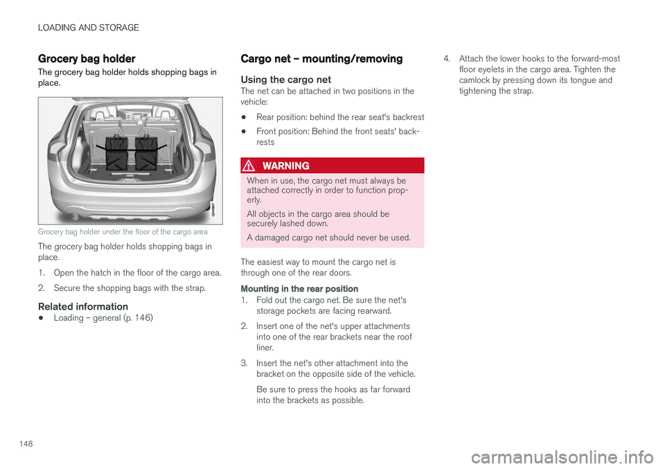
Grocery bag holder
The grocery bag holder holds shopping bags in place.
Grocery bag holder under the floor of the cargo area
The grocery bag holder holds shopping bags in place.
1. Open the hatch in the floor of the cargo area.
2. Secure the shopping bags with the strap.
Related information
• Loading – general (p. 146)
Cargo net – mounting/removing
Using the cargo netThe net can be attached in two positions in the vehicle:
• Rear position: behind the rear seat's backrest
• Front position: Behind the front seats' back-rests
WARNING
When in use, the cargo net must always be attached correctly in order to function prop-erly. All objects in the cargo area should be securely lashed down. A damaged cargo net should never be used.
The easiest way to mount the cargo net is through one of the rear doors.
Mounting in the rear position
1. Fold out the cargo net. Be sure the net's storage pockets are facing rearward.
2. Insert one of the net's upper attachments into one of the rear brackets near the roof liner.
3. Insert the net's other attachment into the bracket on the opposite side of the vehicle. Be sure to press the hooks as far forward into the brackets as possible. 4. Attach the lower hooks to the forward-most
floor eyelets in the cargo area. Tighten thecamlock by pressing down its tongue andtightening the strap.
Page 151 of 404
LOADING AND STORAGE
}}
149
Mounting in the front position
1. Fold out the cargo net. Be sure the net'sstorage pockets are facing rearward.
2. Attaching the net is easier if the front seats are moved as far forward as possible.
3. Insert one of the net's upper attachments into one of the front brackets near the roof liner.
4. Insert the net's other attachment into the bracket on the opposite side of the vehicle. Be sure to press the hooks as far forward into the brackets as possible.
5. Attach the lower hooks to the eyelets on the front seat floor rails. Tighten the camlock bypressing down its tongue and tightening thestrap.
If the front seats are moved rearward, they shouldnot press hard against the net.
CAUTION
When moving the front seats with the cargo net installed, only move the seat(s)/back-rest(s) rearward until they touch the net. Excessive pressure from the front seats against the cargo net could damage the netand/or its brackets.
Removing and storing the cargo net
1. Release the lower hooks.
2. Remove the net's upper attachments from the ceiling brackets.
3. Fold the net.When not in use, the cargo net can be stored under floor of the cargo area.
Related information
• Loading – general (p. 146)
• Steel cargo grid (p. 150)
Cargo area cover
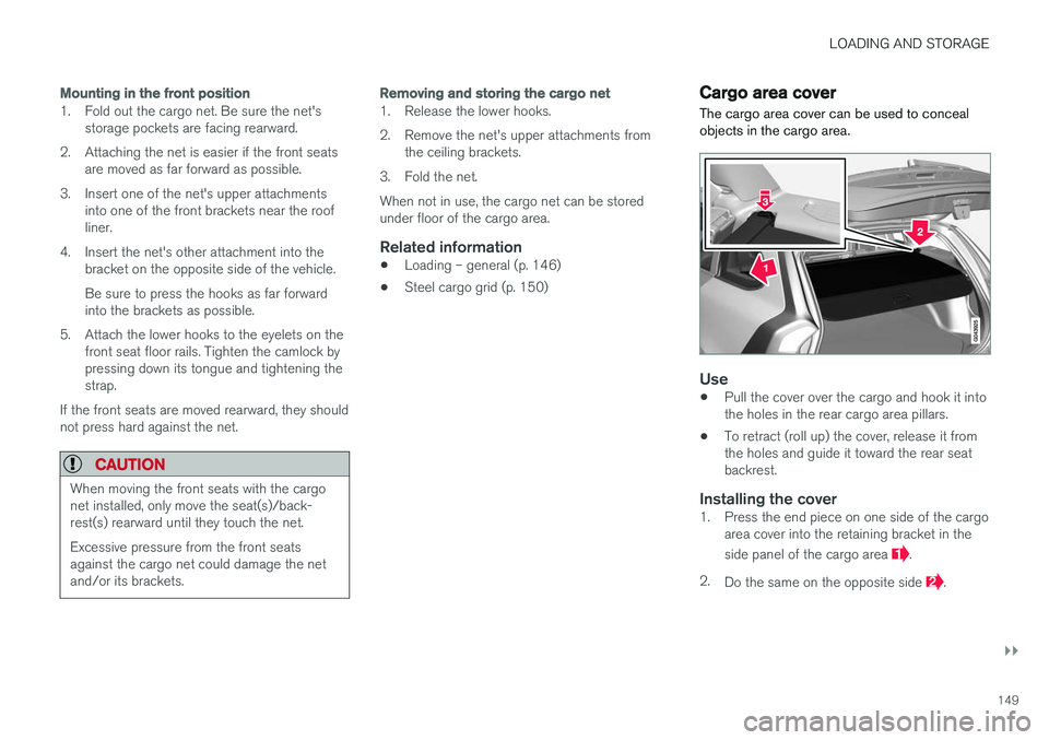
The cargo area cover can be used to conceal objects in the cargo area.
Use
• Pull the cover over the cargo and hook it into the holes in the rear cargo area pillars.
• To retract (roll up) the cover, release it fromthe holes and guide it toward the rear seatbackrest.
Installing the cover1. Press the end piece on one side of the cargo
area cover into the retaining bracket in the side panel of the cargo area
.
2. Do the same on the opposite side
.
Page 293 of 404

STARTING AND DRIVING
}}
* Option/accessory.291
nents, altering emission system components or location or removing components, and/orrepeated use of leaded fuel.
NOTE
Unleaded fuel is required for vehicles with three-way catalytic converters.
Heated oxygen sensorsThe heated oxygen sensors monitor the oxygen content of the exhaust gases. Readings are fedinto a control module that continuously monitorsengine functions and controls fuel injection. Theratio of fuel to air into the engine is continuouslyadjusted for efficient combustion to help reduceharmful emissions.
Related information
•
Information displays – warning symbols(p. 77)
• Engine and cooling system (p. 284)
Economical driving
Better driving economy may be obtained by thinking ahead, avoiding rapid starts and stopsand adjusting the speed of your vehicle to imme-diate traffic conditions.
Economical driving conserves natural
resources
Observe the following rules: • Bring the engine to normal operating tem- perature as soon as possible by driving witha light foot on the accelerator pedal for thefirst few minutes of operation. A cold engineuses more fuel and is subject to increasedwear.
• Whenever possible, avoid using the vehiclefor driving short distances. This does notallow the engine to reach normal operatingtemperature.
• Drive carefully and avoid rapid accelerationand hard braking.
• Use the transmission's Drive (
D) position as
often as possible and avoid using kick-down.
• Using the engine's optional Eco function canhelp improve fuel economy. For additional information, see ECO
* (p. 273).
• Using the transmission's Sport mode may increase fuel consumption somewhat. Use the transmission's Drive (
D) position as often
as possible. For additional information about Sport mode, see Transmission – Geartronic (p. 265).
• Do not exceed posted speed limits.
• Avoid carrying unnecessary items (extra load)in the vehicle.
• Maintain correct tire pressure. Check tirepressure regularly (when tires are cold).
• Remove snow tires when threat of snow orice has ended.
• Note that roof racks, ski racks, etc, increaseair resistance and also fuel consumption.
• At highway driving speeds, fuel consumptionwill be lower with the air conditioning on andthe windows closed than with the air condi-tioning off and the windows open.
• Using the onboard trip computer's fuel con-sumption modes can help you learn how todrive more economically.
Other factors that decrease gas mileage are:
• Dirty air cleaner
• Dirty engine oil and clogged oil filter
• Dragging brakes
• Incorrect front end alignment
Some of the above mentioned items and othersare checked at the standard maintenance inter-vals.
Page 366 of 404

||
MAINTENANCE AND SERVICING
* Option/accessory.
364
Pos Function A
Controls in left rear passenger's door20
Keyless drive
* 7.5
Power driver's seat
*20
Power front passenger's seat
*20
-
Infotainment system display 5
Infotainment system: amplifier, Sir- iusXM
™ satellite radio * 10
Sensus control module 15
Bluetooth hands-free system 5
-
Power moonroof
*
Courtesy lighting, climate system sensor 5
12-volt sockets in tunnel console 15
Heated rear seat
* (passenger's
side) 15
Heated rear seat
* (driver's side) 15
Pos
Function A
-
Heated front passenger's seat*15
Heated driver's seat
*15
Park assist
*
Blind Spot Information System (BLIS) *, park assist camera *5
All Wheel Drive
* control module 15
Active chassis system
*10
Positions: fusebox B
Pos
Function A
Tailgate wiper 15
-
Front courtesy lighting, driver's door power window controls, power seat(s)*, 7.5
Instrument panel 5
Adaptive cruise control/collision warning
* 10
Pos
Function A
Courtesy lighting, rain sensor*,
HomeLInk ®
Wireless Control Sys-
tem * 7.5
Steering wheel module 7.5
Cental locking: fuel filler door 10
Electrically heated steering wheel
*15
Electrically heated windshield
*15
Tailgate unlock 10
Electrical folding rear seat out- board head restraints
*10
Fuel pump 20
Climate system control panel 5
-
Alarm, On-board diagnostic sys- tem
5
Satellite radio
*, audio system
amplifier 10
Airbag system, occupant weight sensor
10
Collision warning system
*5
Page 367 of 404
MAINTENANCE AND SERVICING
* Option/accessory.365
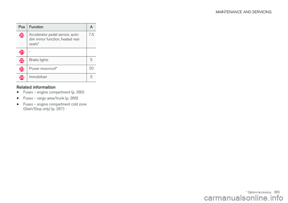
PosFunction A
Accelerator pedal sensor, auto- dim mirror function, heated rear seats* 7.5
-
Brake lights 5
Power moonroof
* 20
Immobilizer 5
Related information
•Fuses – engine compartment (p. 360)
• Fuses – cargo area/trunk (p. 366)
• Fuses – engine compartment cold zone (Start/Stop only) (p. 367)