Page 330 of 404

||
WHEELS AND TIRES
328
WARNING
•Never stand next to the tire being inflated when the compressor is in operation.
• If cracks, bubbles, etc. form on the tire,switch off the compressor immediately.
• If there is visible damage to the sidewall orthe rim, the tire cannot be repaired. Thevehicle should not be driven if this occurs.Contact a towing service, use the Volvo OnCall feature in your vehicle or contact VolvoRoadside Assistance if applicable.
NOTE
The air pressure gauge will temporarily show an increase in pressure to approximately88 psi (6 bar) while the sealing compound isbeing pumped into the tire. The pressureshould return to a normal level after approxi-mately 30 seconds.
9. Within seven minutes, inflate the tire to
between 22—44 psi (1.8—3.0 bar). Switch off the compressor briefly to get a clearreading from the pressure gauge.
CAUTION
The compressor should not be used for more than 10 minutes at a time to avoid overheat-ing.
WARNING
If the pressure remains below 22 psi (1.8 bar) after approximately seven minutes, turn offthe compressor. In this case, the hole is toolarge to be sealed and the vehicle should notbe driven.
10. Switch off the compressor and disconnect the electrical wire from the 12-volt socket.
11. Unscrew the hose from the tire's inflation valve and put the cover on the hose back into place to help prevent seepage of residualsealing compound in the hose. Reinstall thevalve cap.
CAUTION
•After inflating the tires, always reinstall the valve cap to help avoid damage to thevalve from dirt, gravel, etc.
• Use plastic valve caps only. Metal capscould corrode and become difficult toremove.
12. Immediately drive the vehicle for approxi-
mately 2 miles (3 km) at a maximum speed of 50 mph (80 km/h) to distribute the seal-ing compound in the tire.
CAUTION
If your vehicle is equipped with the Tire Pres- sure Monitoring System (TPMS), the use ofthe sealing compound may lead to incorrecttire pressure readings or in rare cases, dam-age to the tire pressure sensor. Use the tiresealing system to check and adjust the dam-aged tire's inflation pressure.
NOTE
• Safely stow the tire sealing system in a convenient place as it will soon be usedagain to check the tire
Page 331 of 404
WHEELS AND TIRES
}}
* Option/accessory.329
WARNING
If heavy vibrations, unsteady steering behavior, or noises should occur while driving, reducespeed and park the vehicle in a safe place.Recheck the tire for bumps, cracks, or othervisible damage, and recheck its inflation pres-sure. If the pressure is below 19 psi (1.3 bar),do not continue driving. Have the vehicletowed to a trained and qualified Volvo servicetechnician.
Tire sealing system – checking inflation pressure The tire sealing system can also be used to check the tires' inflation pressure.
Stage 2: Checking inflation pressure1. Reconnect the tire sealing system's hose to
the tire's inflation valve as described in stage
1 , see Tire sealing system * – sealing a hole
(p. 327).
2. Refer to the inflation pressure table in this chapter for the correct inflation pressure. If the tire needs to be inflated, start the tiresealing system
Page 332 of 404
WHEELS AND TIRES
* Option/accessory.
330
WARNING
• The vehicle
Page 336 of 404
MAINTENANCE AND SERVICING
334
Maintenance – hoisting When the vehicle is hoisted, the jack or garage lift must be positioned in the correct liftingpoints.
Hoisting the vehicle
If a garage jack is used to lift the vehicle, it should be placed: Front: under either of the two reinforced areas
under the front section of the vehicle, not under
to jack attachment points (the outermost points shown in the illustration) .
Rear : Under the jack attachment points.
Ensure that the jack is positioned so that thevehicle cannot slide off it. Always use axle standsor similar structures.Related information
• Changing a wheel – removing wheel (p. 303)
Page 343 of 404

MAINTENANCE AND SERVICING
* Option/accessory.341
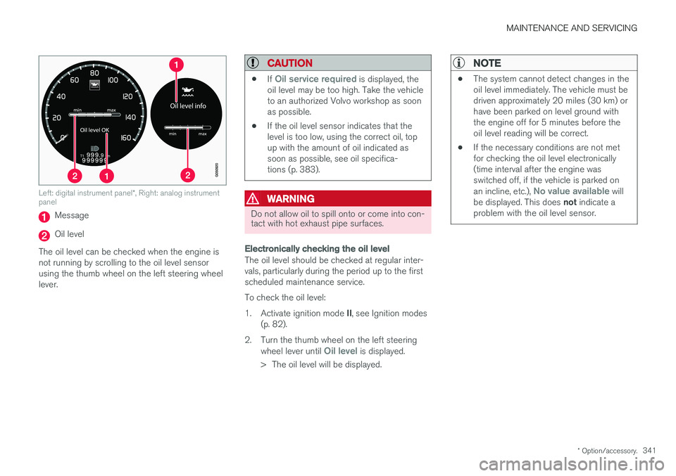
Left: digital instrument panel *, Right: analog instrument
panel
Message
Oil level
The oil level can be checked when the engine is not running by scrolling to the oil level sensorusing the thumb wheel on the left steering wheellever.
CAUTION
• If Oil service required is displayed, the
oil level may be too high. Take the vehicle to an authorized Volvo workshop as soonas possible.
• If the oil level sensor indicates that thelevel is too low, using the correct oil, topup with the amount of oil indicated assoon as possible, see oil specifica-tions (p. 383).
WARNING
Do not allow oil to spill onto or come into con- tact with hot exhaust pipe surfaces.
Electronically checking the oil level
The oil level should be checked at regular inter- vals, particularly during the period up to the firstscheduled maintenance service. To check the oil level:1.
Activate ignition mode II, see Ignition modes
(p. 82).
2. Turn the thumb wheel on the left steering wheel lever until
Oil level is displayed.
> The oil level will be displayed.
NOTE
• The system cannot detect changes in the oil level immediately. The vehicle must bedriven approximately 20 miles (30 km) orhave been parked on level ground withthe engine off for 5 minutes before theoil level reading will be correct.
• If the necessary conditions are not metfor checking the oil level electronically(time interval after the engine wasswitched off, if the vehicle is parked on an incline, etc.),
No value available will
be displayed. This does not indicate a
problem with the oil level sensor.
Page 345 of 404

MAINTENANCE AND SERVICING
}}
343
Engine compartment – brake fluid
The brake fluid should always be between the MIN and MAX marks on the inside of the reser-
voir.
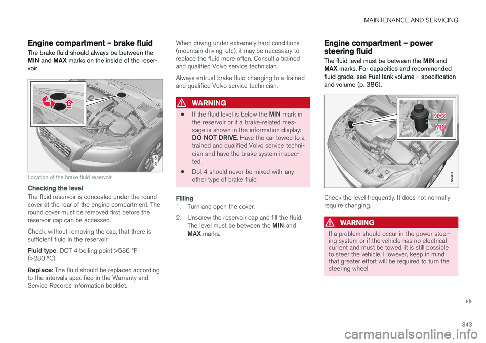
Location of the brake fluid reservoir
Checking the level
The fluid reservoir is concealed under the round cover at the rear of the engine compartment. Theround cover must be removed first before thereservoir cap can be accessed. Check, without removing the cap, that there is sufficient fluid in the reservoir. Fluid type : DOT 4 boiling point >536 °F
(>280 °C).Replace : The fluid should be replaced according
to the intervals specified in the Warranty and Service Records Information booklet. When driving under extremely hard conditions(mountain driving, etc), it may be necessary toreplace the fluid more often. Consult a trainedand qualified Volvo service technician. Always entrust brake fluid changing to a trained and qualified Volvo service technician.
WARNING
•
If the fluid level is below the
MIN mark in
the reservoir or if a brake-related mes- sage is shown in the information display: DO NOT DRIVE . Have the car towed to a
trained and qualified Volvo service techni- cian and have the brake system inspec-ted.
• Dot 4 should never be mixed with anyother type of brake fluid.
Filling
1. Turn and open the cover.
2. Unscrew the reservoir cap and fill the fluid.
The level must be between the MIN and
MAX marks.
Engine compartment – power steering fluid
The fluid level must be between the MIN and
MAX marks. For capacities and recommended
fluid grade, see Fuel tank volume – specification and volume (p. 386).
Check the level frequently. It does not normally require changing.
WARNING
If a problem should occur in the power steer- ing system or if the vehicle has no electricalcurrent and must be towed, it is still possibleto steer the vehicle. However, keep in mindthat greater effort will be required to turn thesteering wheel.
Page 354 of 404

||
MAINTENANCE AND SERVICING
352To put the windshiield wipers in the service posi- tion: 1.
Insert the remote key into the ignition slot 3
and press the START/STOP ENGINE but-
ton briefly to put the ignition in mode I (see
Ignition modes (p. 82) for detailed informa- tion about the ignition modes).
2. Press the START/STOP ENGINE button
again briefly to switch the ignition off.
3. Within 3 seconds, move the right steering wheel lever up and hold it for at least 1 sec-ond.
> The wipers will then move to the vertical(service) position on the windshield.
The wipers can be returned to the normal posi- tion by pressing the START/STOP ENGINE but-
ton briefly to put the ignition in mode I (or by
starting the engine).
CAUTION
If the wiper arms have been folded out from the windshield while in the service position,fold them back against the windshield beforereturning the wipers to the normal position tohelp avoid scratching the paint on the hood.
Related information
• Engine compartment – washer fluid (p. 354)
Wiper blades – windshield The wiper blades should be replaced regularly for best effect. The windshield wiper blades must be in the verti- cal (service) position for replacement, washingor to lift them away from the windshield whene.g., removing ice or snow.
Replacing the windshield wiper blades
NOTE
The windshield wiper blades are different lengths. The blade on the driver
Page 366 of 404

||
MAINTENANCE AND SERVICING
* Option/accessory.
364
Pos Function A
Controls in left rear passenger's door20
Keyless drive
* 7.5
Power driver's seat
*20
Power front passenger's seat
*20
-
Infotainment system display 5
Infotainment system: amplifier, Sir- iusXM
™ satellite radio * 10
Sensus control module 15
Bluetooth hands-free system 5
-
Power moonroof
*
Courtesy lighting, climate system sensor 5
12-volt sockets in tunnel console 15
Heated rear seat
* (passenger's
side) 15
Heated rear seat
* (driver's side) 15
Pos
Function A
-
Heated front passenger's seat*15
Heated driver's seat
*15
Park assist
*
Blind Spot Information System (BLIS) *, park assist camera *5
All Wheel Drive
* control module 15
Active chassis system
*10
Positions: fusebox B
Pos
Function A
Tailgate wiper 15
-
Front courtesy lighting, driver's door power window controls, power seat(s)*, 7.5
Instrument panel 5
Adaptive cruise control/collision warning
* 10
Pos
Function A
Courtesy lighting, rain sensor*,
HomeLInk ®
Wireless Control Sys-
tem * 7.5
Steering wheel module 7.5
Cental locking: fuel filler door 10
Electrically heated steering wheel
*15
Electrically heated windshield
*15
Tailgate unlock 10
Electrical folding rear seat out- board head restraints
*10
Fuel pump 20
Climate system control panel 5
-
Alarm, On-board diagnostic sys- tem
5
Satellite radio
*, audio system
amplifier 10
Airbag system, occupant weight sensor
10
Collision warning system
*5