Page 97 of 166

PRACTICAL INFORMATION
}}
95
Tread wear indicatorThe tires have wear indicator strips running across or parallel to the tread.
The letters TWI are printed on the side of the tire. When approximately 1/16" (1.6 mm) is left onthe tread, these strips become visible and indi-cate that the tire should be replaced. Tires withless than 1/16" (1.6 mm) tread offer very poortraction. When replacing worn tires, it is recommended that the tire be identical in type (radial) and sizeas the one being replaced. Using a tire of thesame make (manufacturer) will help preventalteration of the driving characteristics of thevehicle.
Related information
• Tire direction of rotation (p. 94)
• Checking tire inflation pressure (p. 97)
Loading specifications Properly loading your vehicle will provide maxi- mum return of vehicle design performance.
Weight designations
Before loading your vehicle, familiarize yourself with the following terms for determining yourvehicle's weight ratings, with or without a trailer,from the vehicle's Federal/Canadian Motor Vehi-cle Safety Standards (FMVSS/CMVSS) label, andthe vehicle's tire information placard:
Curb weight
The weight of the vehicle including a full tank of fuel and all standard equipment. It does notinclude passengers, cargo, or optional equipment.
Capacity weight
All weight added to the curb weight, including cargo and optional equipment. When towing,trailer hitch tongue load is also part of cargoweight.
Permissible axle weight
The maximum allowable weight that can be car- ried by a single axle (front or rear). These num-bers are shown on the Federal/Canadian MotorVehicle Safety Standards (FMVSS/CMVSS) label.The total load on each axle must never exceed itsmaximum permissible weight.
Gross vehicle weight (GVW)
The vehicle's curb weight + cargo + passengers.
Steps for Determining Correct Load Limit
1. Locate the statement "the combined weight
of occupants and cargo should never exceed XXX kg or XXX lbs." on your vehicle's plac-ard.
2. Determine the combined weight of the driver and passengers that will be riding in yourvehicle.
3. Subtract the combined weight of the driver and passengers from XXX kg or XXX lbs.
4. The resulting figure equals the available amount of cargo and luggage load capacity.For example, if the "XXX" amount equals1400 lbs. and there will be five 150 lb. pas-sengers in your vehicle, the amount of availa-ble cargo and luggage load capacity is650 lbs. (1400 – 750 (5 × 150) = 650 lbs.)
5. Determine the combined weight of luggage and cargo being loaded on the vehicle. Thatweight may not safely exceed the availablecargo and luggage load capacity calculatedin Step 4.
6. If your vehicle will be towing a trailer, load from your trailer will be transferred to yourvehicle. Consult this manual to determinehow this reduces the available cargo and lug-gage load capacity of your vehicle.
Page 101 of 166

PRACTICAL INFORMATION
* Option/accessory.99
NOTE
•If you overfill the tire, release air by push- ing on the metal stem in the center of thevalve. Then recheck the pressure withyour tire gauge.
• Some spare tires require higher inflationpressure than the other tires. Consult thetire inflation pressure table or the inflationpressure placard.
Changing tires
When changing wheels to another dimension, always follow Volvo's instructions.
When changing to tires of another
dimension
If you mount tires with a dimension other thanthe factory-installed tires, contact an authorizedVolvo retailer to update the vehicle's software.This may also be necessary when changing fromsummer to winter tires, or vice versa.
Related information
• Snow tires and chains (p. 97)
• Installing a wheel (p. 102)
• Removing a wheel (p. 101)
Tools
Tools for e.g., changing wheels, etc., are located under the floor of the trunk.
Generic illustration - the appearance and location of the foam block may vary from model to model
The foam block under the floor of the trunk con- tains the towing eyelet, the tool for removing plastic wheel bolt covers, the jack * and the lug
wrench *. There is also a storage space for the
tool used to remove locking wheel bolts.
Related information
• Jack (p. 100)
• Changing tires (p. 99)
Page 104 of 166

||
PRACTICAL INFORMATION
1025.
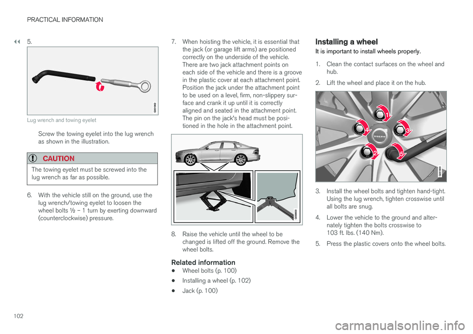
Lug wrench and towing eyelet
Screw the towing eyelet into the lug wrench as shown in the illustration.
CAUTION
The towing eyelet must be screwed into the lug wrench as far as possible.
6. With the vehicle still on the ground, use the
lug wrench/towing eyelet to loosen the wheel bolts ½ – 1 turn by exerting downward(counterclockwise) pressure. 7. When hoisting the vehicle, it is essential that
the jack (or garage lift arms) are positionedcorrectly on the underside of the vehicle.There are two jack attachment points oneach side of the vehicle and there is a groovein the plastic cover at each attachment point.Position the jack under the attachment pointto be used on a level, firm, non-slippery sur-face and crank it up until it is correctlyaligned and seated in the attachment point.The pin on the jack's head must be posi-tioned in the hole in the attachment point.
8. Raise the vehicle until the wheel to bechanged is lifted off the ground. Remove the wheel bolts.
Related information
• Wheel bolts (p. 100)
• Installing a wheel (p. 102)
• Jack (p. 100)
Installing a wheel
It is important to install wheels properly.
1. Clean the contact surfaces on the wheel and hub.
2. Lift the wheel and place it on the hub.
3. Install the wheel bolts and tighten hand-tight. Using the lug wrench, tighten crosswise until all bolts are snug.
4. Lower the vehicle to the ground and alter- nately tighten the bolts crosswise to103 ft. lbs. (140 Nm).
5. Press the plastic covers onto the wheel bolts.