2018 VOLVO S60 INSCRIPTION change wheel
[x] Cancel search: change wheelPage 243 of 396
DRIVER SUPPORT
}}
241
Automatic zoom
Automatic zoom is a feature that is available on
models equipped with a trailer hitch and the optional (p. 230)Park assist system. With thisalternative selected, the camera will zoom in onthe trailer hitch automatically if the vehicleapproaches an object/trailer. See also the "Settings" section below.
DeactivationMove the gear selector from R to another gear.
The camera remains active for approx. 5 seconds after the gear selector has been moved from R or
until the vehicle's forward speed exceeds 6 mph/10 km/h (21 mph/35 km/h in reverse).The screen will then revert to the view that was displayed before R was selected.
NOTE
If any button on the center console control panel is pressed, the camera image will disap- pear from the display. Pressing CAM will
return the camera image to the display.
SettingsBy default, PAC is set to activate when the gear selector is moved to R
To change PAC settings when a camera view is displayed: 1.
Press OK/MENU when a camera view is on
the screen. A menu will be displayed.
2. Turn TUNE to scroll to the desired setting.
3. Press OK/MENU to make the setting and
exit the menu by pressing EXIT.
Summary
•Pressing
CAM will activate the camera even
if the gear selector is not in Reverse.
• Toggle between normal view and zoom by pressing
CAM or by turning TUNE.
Related information
•Park assist – introduction (p. 230)
• Park assist – function (p. 230)
• Park assist – troubleshooting (p. 238)
• Park assist – limitations (p. 233)
• Rear Park Assist Camera (PAC) – introduc- tion (p. 239)
Rear Park Assist Camera (PAC) – guiding and marker lines
Guiding lines
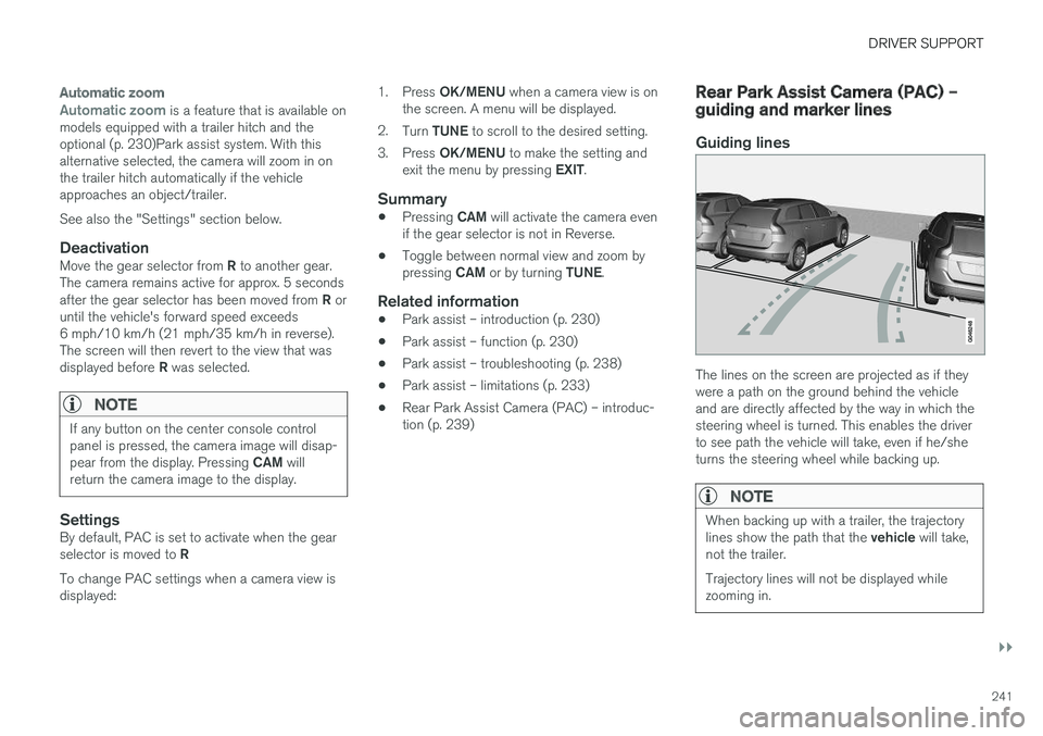
The lines on the screen are projected as if they were a path on the ground behind the vehicleand are directly affected by the way in which thesteering wheel is turned. This enables the driverto see path the vehicle will take, even if he/sheturns the steering wheel while backing up.
NOTE
When backing up with a trailer, the trajectory lines show the path that the
vehicle will take,
not the trailer. Trajectory lines will not be displayed while zooming in.
Page 260 of 396
||
STARTING AND DRIVING
* Option/accessory.
258
Geartronic : steering wheel paddles *
In addition to the manual gearshift function using the gear selector, this option makes it possible tomanually shift gears from the steering wheel.
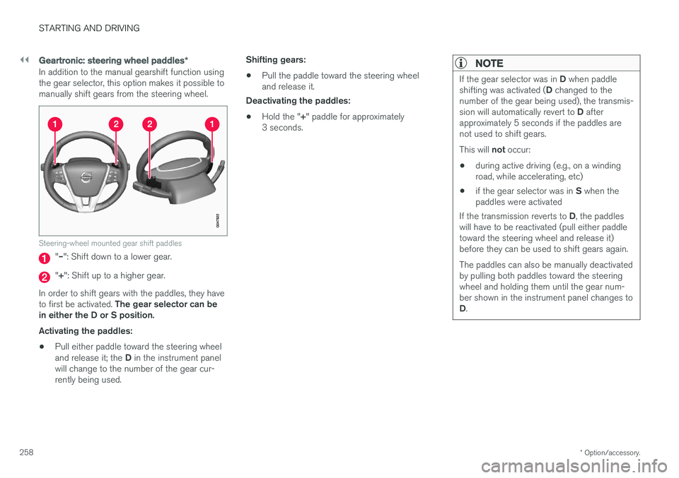
Steering-wheel mounted gear shift paddles
"– ": Shift down to a lower gear.
"+ ": Shift up to a higher gear.
In order to shift gears with the paddles, they have to first be activated. The gear selector can be
in either the D or S position. Activating the paddles:
• Pull either paddle toward the steering wheel and release it; the
D in the instrument panel
will change to the number of the gear cur- rently being used. Shifting gears:
• Pull the paddle toward the steering wheeland release it.
Deactivating the paddles:
• Hold the "
+" paddle for approximately
3 seconds.
NOTE
If the gear selector was in D when paddle
shifting was activated ( D changed to the
number of the gear being used), the transmis- sion will automatically revert to D after
approximately 5 seconds if the paddles are not used to shift gears. This will not occur:
• during active driving (e.g., on a winding road, while accelerating, etc)
• if the gear selector was in
S when the
paddles were activated
If the transmission reverts to D, the paddles
will have to be reactivated (pull either paddletoward the steering wheel and release it)before they can be used to shift gears again. The paddles can also be manually deactivated by pulling both paddles toward the steeringwheel and holding them until the gear num-ber shown in the instrument panel changes to D .
Page 268 of 396
||
STARTING AND DRIVING
* Option/accessory.
266 This feature is primarily intended to be used in driving situations where a decrease in speed isexpected, such as when entering a zone with alower speed limit. Eco Coast enables proactive driving with as little braking as possible.
Combinations of On and Off
Depending on the driving situation, Eco can be used in different ways to help reduce fuel con-sumption:
• With Eco activated
: this enables Eco Coast,
which allows the vehicle to roll freely for as
far as possible when the driver releases the
accelerator pedal (e.g., when approaching atraffic light or intersection).
or
• With Eco deactivated
: engine braking can
be used when the vehicle will only roll for
a short distance (in heavy traffic, etc.) or
when driving down hills .
To help keep fuel consumption as low as possi-ble, Eco Coast should not be used in traffic situa-tions where the brakes have to be used fre-quently.
Activating Eco Coast
Eco Coast is activated when the accelerator pedal is released completely if:
• Eco is activated
• The gear selector is in
D •
The vehicle's speed is between approxi-mately 40–85 mph (65–140 km/h). Alwaysobserve posted speed limits
• The gradient of a down-slope is less thanapproximately 6%
Deactivating
Eco Coast
In certain situations, it may be advisable to switch off the Eco Coast function, such as:
• When driving down steep hills, in order to uti-lize engine braking
• Prior to passing another vehicle, in order todo so as safely as possible
Deactivating Eco Coast (and reactivating enginebraking) can be done in the following ways: • Press the
ECO button on the center console
• Move the gear selector to the manual "
S+/–"
position
• Change gears using the steering wheel pad- dles
*
• Press the brake or accelerator pedal
Eco Coast limitationsThis function will not be available if:
• Cruise control is activated
• The gradient of a down-slope is more than approximately 6%
• The steering wheel paddles
* are used to
manually change gears •
The engine and/or transmission have notreached their normal operating temperature
• The gear selector is moved from
D to the
manual " S+/–" position
• The vehicle's speed is not within the40–85 mph (65–140 km/h). interval
Additional information and settings
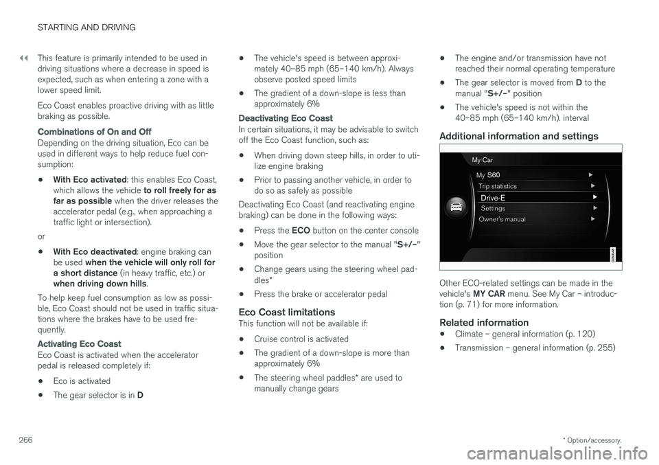
Other ECO-related settings can be made in the vehicle's
MY CAR menu. See My Car – introduc-
tion (p. 71) for more information.
Related information
• Climate – general information (p. 120)
• Transmission – general information (p. 255)
Page 295 of 396
WHEELS AND TIRES
}}
* Option/accessory.293
Changing a wheel – direction of rotation Incorrectly mounted tires impair the car's braking properties and ability to force aside rain, snowand slush.
Summer and winter tires
G021778
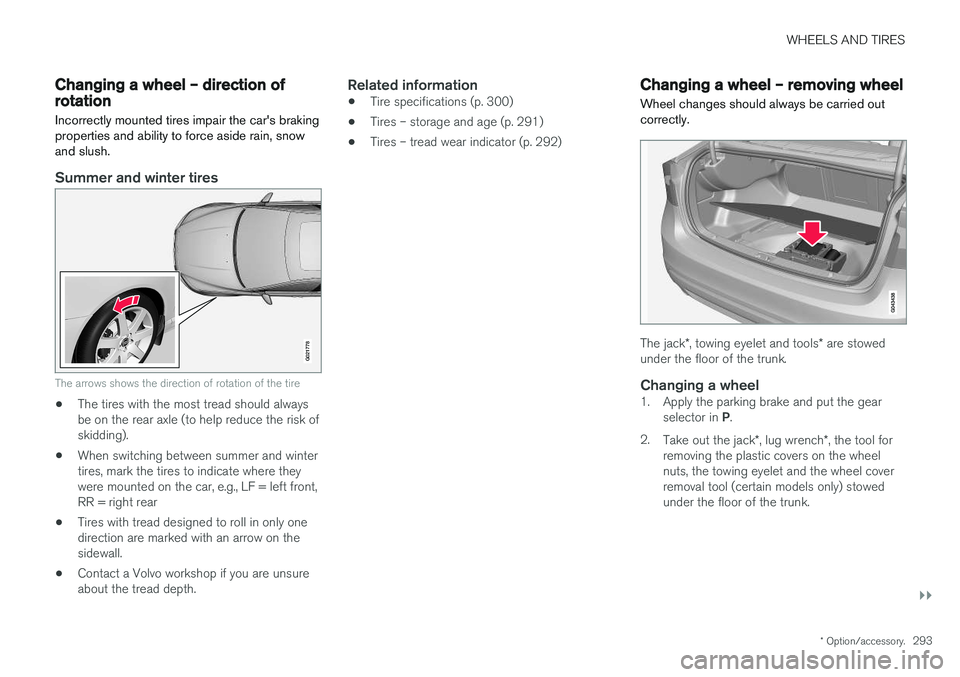
The arrows shows the direction of rotation of the tire
•The tires with the most tread should always be on the rear axle (to help reduce the risk ofskidding).
• When switching between summer and wintertires, mark the tires to indicate where theywere mounted on the car, e.g., LF = left front,RR = right rear
• Tires with tread designed to roll in only onedirection are marked with an arrow on thesidewall.
• Contact a Volvo workshop if you are unsureabout the tread depth.
Related information
•Tire specifications (p. 300)
• Tires – storage and age (p. 291)
• Tires – tread wear indicator (p. 292)
Changing a wheel – removing wheel Wheel changes should always be carried out correctly.
The jack
*, towing eyelet and tools * are stowed
under the floor of the trunk.
Changing a wheel1. Apply the parking brake and put the gear
selector in P.
2. Take out the jack *, lug wrench *, the tool for
removing the plastic covers on the wheel nuts, the towing eyelet and the wheel coverremoval tool (certain models only) stowedunder the floor of the trunk.
Page 297 of 396

WHEELS AND TIRES
295
7. There are two jack attachment points on
each side of the vehicle. Position the jack under the attachment point to be used on alevel, firm, non-slippery surface and crank itup until it is correctly aligned and seated inthe attachment point. Before raising the vehi-cle, check that the jack is still correctly posi-tioned in the attachment.
8. Raise the vehicle until the wheel to be changed is lifted off the ground.
9. Unscrew the wheel nuts completely and remove the wheel.
WARNING
• The jack must correctly engage the jack attachment.
• Be sure the jack is on a firm, level, non-slippery surface.
• Never allow any part of your body to beextended under a vehicle supported by ajack.
• Use the jack intended for the vehiclewhen changing a tire. For any other job,use stands to support the vehicle.
• Apply the parking brake and put the gear selector in the Park (
P) position.
• Block the wheels standing on the ground, use rigid wooden blocks or large stones.
• The jack should be kept well-greased andclean, and should not be damaged.
• No objects should be placed between thebase of jack and the ground, or betweenthe jack and the attachment bar on thevehicle.
NOTE
The jack provided with your vehicle is intended to be used only in temporary situa-tions such as changing wheels in the event ofa flat tire. Only the jack that came with yourparticular model should be used to lift thevehicle. If the vehicle needs to be lifted morefrequently or for a prolonged period, using agarage jack or hoist is recommended. Alwaysfollow this device
Page 298 of 396

WHEELS AND TIRES
* Option/accessory.
296
Changing a wheel – spare wheel Wheel changes should always be carried out correctly.
Spare tireA spare tire can be purchased for your vehicle as an accessory. Follow the instructions includedwith the spare tire regarding use and stowing inthe vehicle. See also Changing a wheel – remov-ing wheel (p. 293) for additional information.
Spare wheelThe following instructions only apply if you have purchased a temporary spare wheel * for your
vehicle. If there is no temporary spare wheel in your vehi- cle, please see Tire sealing system * – general
information (p. 314) for instructions on using the tire sealing system. The accessory temporary spare wheel is provided in a bag that must be securely strapped in placein the trunk while the vehicle is being driven. The spare wheel is only intended for temporary use. Replace it with a normal wheel as soon aspossible. The vehicle's handling may be alteredby the use of the spare wheel. The correct tirepressure is stated in the tire pressure table, seethe tire inflation decal on the driver's door open-ing.Turn the handle on the spare wheel bag in toward the rear seat. Secure the stitched straphooks in the loading eyelets. Secure the longstrap in one of the loading eyelets, wrap the straparound the spare wheel and through the lowerhandle. Secure the short strap on the long strap.Secure in the other loading eyelet and tighten.
WARNING
Current legislation prohibits the use of the “Temporary Spare” tire other than as a tempo-rary replacement for a punctured tire. It mustbe replaced as soon as possible by a stand-ard tire. Road holding and handling may beaffected with the “Temporary Spare” in use.
CAUTION
The vehicle must never be driven with more than one temporary spare wheel.
Related information
• Changing a wheel – installing a wheel (p. 297)
• Changing a wheel – removing wheel (p. 293)
Page 299 of 396
WHEELS AND TIRES
}}
* Option/accessory.297
Changing a wheel – accessing the spare wheel
The following procedure explains how to access the spare wheel (where applicable).
1. Release the bag's retaining straps.
2. Lift the bag out of the vehicle and remove the spare wheel from the bag.
3. Fold up the floor hatch in the trunk.4. Remove the jack * and tools * from the foam
block and change the wheels (see the instructions in the following section "Chang-ing a wheel").
5. After changing wheels, return the jack and tools to the foam block and close the floorhatch.
6. If possible, place the wheel with the punc- tured tire in the bag. 7. If there is a wheel in the bag, strap the bag
securely in place in the trunk.
WARNING
•If there is a wheel in the bag, the bag must be securely restrained using its straps andthe load anchoring eyelets in the trunk.See (p. 296) and carefully follow theinstructions.
• If the wheel with the punctured tire is toobig to fit in the bag, it should be securelyrestrained in the trunk using suitablestraps, a net for anchoring cargo, etc.
Changing a wheel – installing a wheel
It is important to re-install wheels properly.
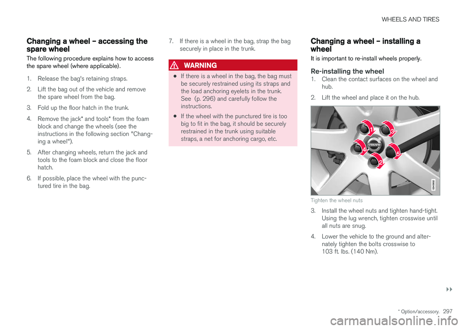
Re-installing the wheel1. Clean the contact surfaces on the wheel and hub.
2. Lift the wheel and place it on the hub.
Tighten the wheel nuts
3. Install the wheel nuts and tighten hand-tight. Using the lug wrench, tighten crosswise until all nuts are snug.
4. Lower the vehicle to the ground and alter- nately tighten the bolts crosswise to103 ft. lbs. (140 Nm).
Page 300 of 396
||
WHEELS AND TIRES
2985. Press the plastic covers onto the wheel nuts
and Install the wheel cover (where applica- ble). The opening in the wheel cover for thetire's inflation valve must be positioned overthe valve.
Related information
• Changing a wheel – spare wheel (p. 296)
• Changing a wheel – removing wheel (p. 293)
Tire inflation – general information
Check tire inflation pressure regularly.
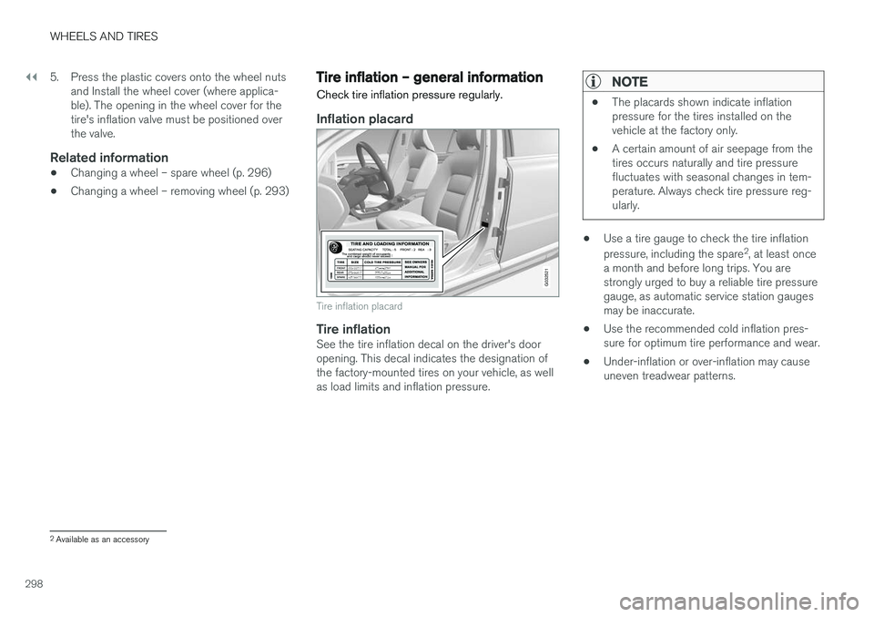
Inflation placard
G032521
Tire inflation placard
Tire inflationSee the tire inflation decal on the driver's door opening. This decal indicates the designation ofthe factory-mounted tires on your vehicle, as wellas load limits and inflation pressure.
NOTE
• The placards shown indicate inflation pressure for the tires installed on thevehicle at the factory only.
• A certain amount of air seepage from thetires occurs naturally and tire pressurefluctuates with seasonal changes in tem-perature. Always check tire pressure reg-ularly.
•Use a tire gauge to check the tire inflation pressure, including the spare 2
, at least once
a month and before long trips. You are strongly urged to buy a reliable tire pressuregauge, as automatic service station gaugesmay be inaccurate.
• Use the recommended cold inflation pres-sure for optimum tire performance and wear.
• Under-inflation or over-inflation may causeuneven treadwear patterns.
2
Available as an accessory