2018 SUBARU WRX trailer
[x] Cancel search: trailerPage 409 of 578

(422,1)
北米Model "A1700BE-B" EDITED: 2017/ 10/ 11
rected, and the BSD/RCTA warning
indicator will disappear. However, if
the BSD/RCTA warning indicator
appears for a prolonged period of
time, have the system inspected at a
SUBARU dealer as soon as possible.
.The detectability of the radar sen-
sors is restricted. The BSD/RCTA de-
tection may be impaired and the system
may not operate properly under the
following conditions.
–When the rear bumper around the
radar sensors is distorted
–When ice, snow or mud adheres
to the rear bumper surface around
the radar sensors
–When stickers, etc. are affixed on
the areas of the radar sensors on
the rear bumper
–During adverse weather condi-
tions such as rain, snow or fog
–When driving on wet roads such
as snow-covered roads and through
puddles
.The radar sensors may not detect or
may have difficulty detecting the fol-
lowing vehicles and objects.
–Small motorcycles, bicycles, pe-
destrians, stationary objects on the
road or road side and etc.
–Vehicles with body shapes thatthe radar may not reflect (vehicles
with lower body height such as
sports cars or a trailer with no
cargo)
–Vehicles that are not approaching
your vehicle even though they are in
the detection area (either on a
neighboring lane to the rear or be-
side your vehicle when reversing)
(The system determines the pre-
sence of approaching vehicles
based on data detected by the radar
sensors.)
–Vehicles traveling at significantly
different speeds
–Vehicles driving in parallel at al-
most the same speed as your vehi-
cle for a prolonged time
–Oncoming vehicles
–Vehicles in a lane beyond the
neighboring lane
–Vehicles travelling at a signifi-
cantly lower speed that you are
trying to overtake
.On a road with extremely narrow
lanes, the system may detect vehicles
driving in a lane next to the neighboring
lane.
&BSD/RCTA approach indica-
tor light/warning buzzerWhile the BSD/RCTA is active, the follow-
ing item(s) will operate to alert the driver:
.The BSD/RCTA approach indicator
light (when there are vehicles in the
neighboring lanes).
.The BSD/RCTA approach indicator
light and warning buzzer (when a vehicle
is approaching from the left or right side
while reversing)
!BSD/RCTA approach indicator lightBSD/RCTA approach indicator lightIt is mounted on each side of the outside
mirrors.
The indicator light will illuminate when a
vehicle approaching from behind is de-
Starting and operating/BSD/RCTA
7-60
Page 426 of 578

(441,1)
北米Model "A1700BE-B" EDITED: 2017/ 10/ 11
New vehicle break-in driving–the first 1,000
miles (1,600 km)...................................................8-2
Fuel economy hints................................................8-2
Engine exhaust gas (carbonmonoxide)............... 8-2
Catalytic converter..................................................8-3
Periodic inspections...............................................8-4
Driving in foreigncountries...................................8-4
Driving tips for AWD models.................................8-5
Driving precaution..................................................8-6
Winter driving..........................................................8-6
Operation during cold weather............................... 8-6
Driving on snowy and icy roads............................. 8-8
Corrosion protection.............................................. 8-9Snow tires..............................................................8-9
Tire chains...........................................................8-10
Rocking the vehicle..............................................8-10
Loading your vehicle.............................................8-11
Vehicle capacity weight........................................8-12
GVWR and GAWR (Gross Vehicle Weight Rating
and Gross Axle Weight Rating)..........................8-12
Precautions for TYPE RA......................................8-13
Roof molding and crossbar (if equipped)..............8-13
Trailer towing........................................................8-14
Rear wing (TYPERA)...........................................8-15
Adjusting the angle of the rear wing.....................8-15
CFRP (Carbon Fiber Reinforced Plastic) parts.......8-16
Driving tips
8
Page 439 of 578

(454,1)
北米Model "A1700BE-B" EDITED: 2017/ 10/ 11
heaviest load at the bottom, close to the
roof, and evenly distribute the cargo.
Always properly secure all cargo.
!Installing carrying attachments on
the crossbars
When installing any carrying attachments
such as the load carriers, crossbars, bike
carrier, ski carrier, kayak carrier, cargo
basket, etc., follow the manufacturer’s
instructions of the load capacity and make
sure that the attachments are securely
installed. Use only attachments designed
specifically for the crossbars. Before oper-
ating the vehicle, make sure that the cargo
is properly secured on the attachment.NOTERemember that the vehicle’s center of
gravity is altered with the weight of the
load on the roof, thus affecting the
driving characteristics.
Drive carefully. Avoid rapid starts, hard
cornering and abrupt stops. Crosswind
effects will be increased.!Removal and installation of the
crossbars
Each of the two roof moldings has two
mounting points for crossbars. Each
mounting point is fitted with a cover. Use
a screwdriver to remove the covers. When
installing the crossbars on the roof mold-
ing, follow the manufacturer’s instructions.
Trailer towing
CAUTION
Your vehicle is neither designed nor
intended to be used for trailer tow-
ing. Therefore, never tow a trailer
with your vehicle.
SUBARU assumes no responsibility for
injuries or vehicle damage that may result
from trailer towing, from any trailer towing
equipment or from any errors or omissions
in the instructions accompanying such
equipment. SUBARU warranties do not
apply to vehicle damage or malfunction
caused by trailer towing.
Driving tips/Trailer towing
8-14
Page 451 of 578
(468,1)
北米Model "A1700BE-B" EDITED: 2017/ 10/ 11
.Do not tow a trailer.
.If used for a purpose other than
sealing a flat tire, the flat tire
repair kit may cause a severe
accident or injury due to the fact
that compressed air can act as an
explosive or propellant.
.Safely park your vehicle on the
roadside so that you do not
obstruct the flow of traffic and
so that you are able to seal the flat
tire without being in danger.
.Apply the parking brake, even if
the vehicle is parked on a level
road, to make sure that the vehi-
cle will not move.
.Stop the engine before sealing
the flat tire.
.Turn on the hazard warning
flasher while sealing the flat tire.
.Do not attempt to remove foreign
objects like nails or screws that
have penetrated the tire. Leave
them as they are.
.Never leave the flat tire repair kit
unattended while in use.
.Only one tire can be repaired with
one bottle of sealant.
.The tires can be repaired when
the ambient temperature is�228F(�308C) or higher.
CAUTION
.Remember that the flat tire repair
kit only provides temporary mo-
bility. Regulations concerning
tire repair after usage of flat tire
repair kit may differ from country
to country. We recommend that
you consult your SUBARU dealer
or tire dealer for advice.
.Store the flat tire repair kit safely
and secure it in the cargo area.
Storing it anywhere in the pas-
senger compartment is not advi-
sable because it could strike an
occupant in the event of a sudden
stop or collision and cause injury.
.Use the flat tire repair kit with
original vehicle tires only.
.Do not keep the air compressor
operating for more than 10 min-
utes, otherwise there is a risk of
overheating.
.The temperature of the air com-
pressor may become high. Be
careful not to burn yourself.
.When raining, take measures to
prevent the air compressor frombeing exposed directly to the
rain. Exposing to rain may cause
a malfunction.
.Do not use air compressors other
than the one in the repair kit.
Using an air compressor other
than the one in the repair kit may
damage the tires.
.Do not disassemble or modify the
air compressor to enable the use
of a power supply or a battery
other than DC12V.
.If a temporary puncture repair is
performed with the repair kit, the
Tire Pressure Monitoring System
(TPMS) may not operate nor-
mally.
In case of emergency/Flat tires
9-10
Page 456 of 578
(473,1)
北米Model "A1700BE-B" EDITED: 2017/ 10/ 11
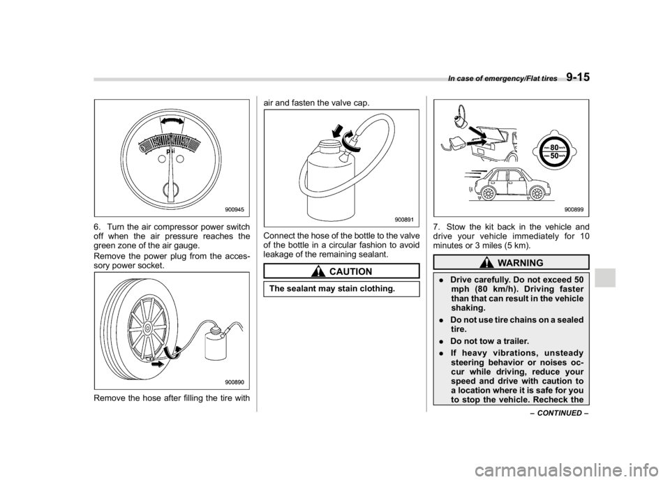
6. Turn the air compressor power switch
off when the air pressure reaches the
green zone of the air gauge.
Remove the power plug from the acces-
sory power socket.Remove the hose after filling the tire withair and fasten the valve cap.
Connect the hose of the bottle to the valve
of the bottle in a circular fashion to avoid
leakage of the remaining sealant.
CAUTION
The sealant may stain clothing.
7. Stow the kit back in the vehicle and
drive your vehicle immediately for 10
minutes or 3 miles (5 km).
WARNING
.Drive carefully. Do not exceed 50
mph (80 km/h). Driving faster
than that can result in the vehicle
shaking.
.Do not use tire chains on a sealed
tire.
.Do not tow a trailer.
.If heavy vibrations, unsteady
steering behavior or noises oc-
cur while driving, reduce your
speed and drive with caution to
a location where it is safe for you
to stop the vehicle. Recheck the
–CONTINUED–
In case of emergency/Flat tires
9-15
9
Page 557 of 578
(582,1)
北米Model "A1700BE-B" EDITED: 2017/ 10/ 11
&Tire care–maintenance and
safety practices.
Check on a daily basis that the
tires are free from serious damage,
nails, and stones. At the same time,
check the tires for abnormal wear.
.
Inspect the tire tread regularly
and replace the tires before their
tread wear indicators become visi-
ble. When a tire’s tread wear in-
dicator becomes visible, the tire is
worn beyond the acceptable limit
and must be replaced immediately.
With a tire in this condition, driving
at even low speeds in wet weather
can cause the vehicle to hydro-
plane. Possible resulting loss of
vehicle control can lead to an
accident.
.
Replace any damaged or un-
evenly worn tires at the time of
rotation. For information about the
tire rotation order, refer to“
Tire
rotation”F11-36.
After tire rotation,
adjust the tire pressures and make
sure the wheel nuts are correctly
tightened. For information aboutthe tightening torque and tighten-
ing sequence for the wheel nuts,
refer to“
Flat tires”F9-5.
&Vehicle load limit–how to
determineThe load capacity of your vehicle is
determined by weight, not by avail-
able cargo space. The load limit of
your vehicle is shown on the vehicle
placard attached to the driver’s side
B-pillar. Locate the statement“The
combined weight of occupants and
cargo should never exceed XXX kg
or XXX lbs”on your vehicle’s
placard.
The vehicle placard also shows
seating capacity of your vehicle.
The total load capacity includes the
total weight of driver and all pas-
sengers and their belongings, any
cargo, any optional equipment such
as a roof rack or bike carrier, etc.
Therefore cargo capacity can be
calculated by the following method.
Cargo capacity = Load limit�(totalweight of occupants + total weight
of optional equipment)
For information about vehicle load-
ing, refer to“
Loading your vehicle”
F8-11.CAUTION
Your vehicle is neither de-
signed nor intended to be
used for trailer towing. There-
fore, never tow a trailer with
your vehicle.
Consumer information and Reporting safety defects/Tire information
13-10
Page 559 of 578
(584,1)
北米Model "A1700BE-B" EDITED: 2017/ 10/ 11
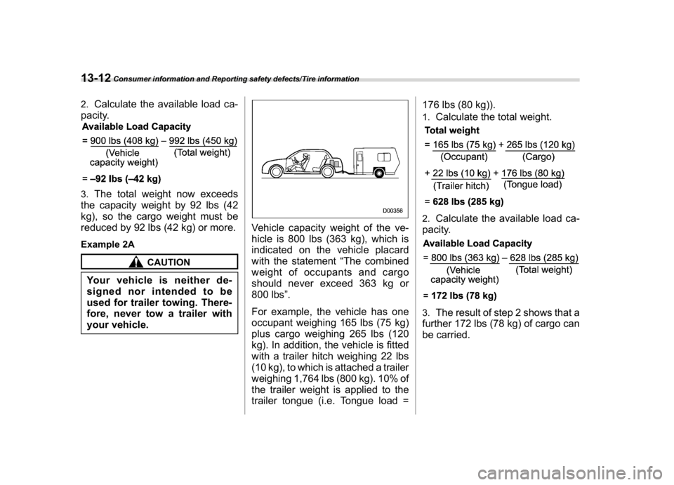
2.
Calculate the available load ca-
pacity.
3.
The total weight now exceeds
the capacity weight by 92 lbs (42
kg), so the cargo weight must be
reduced by 92 lbs (42 kg) or more.
Example 2A
CAUTION
Your vehicle is neither de-
signed nor intended to be
used for trailer towing. There-
fore, never tow a trailer with
your vehicle.
Vehicle capacity weight of the ve-
hicle is 800 lbs (363 kg), which is
indicated on the vehicle placard
with the statement“The combined
weight of occupants and cargo
should never exceed 363 kg or
800 lbs”.
For example, the vehicle has one
occupant weighing 165 lbs (75 kg)
plus cargo weighing 265 lbs (120
kg). In addition, the vehicle is fitted
with a trailer hitch weighing 22 lbs
(10 kg), to which is attached a trailer
weighing 1,764 lbs (800 kg). 10% of
the trailer weight is applied to the
trailer tongue (i.e. Tongue load =176 lbs (80 kg)).
1.
Calculate the total weight.
2.
Calculate the available load ca-
pacity.
3.
The result of step 2 shows that a
further 172 lbs (78 kg) of cargo can
be carried.
Consumer information and Reporting safety defects/Tire information
13-12
Page 560 of 578
(585,1)
北米Model "A1700BE-B" EDITED: 2017/ 10/ 11
Example 2B
CAUTION
Your vehicle is neither de-
signed nor intended to be
used for trailer towing. There-
fore, never tow a trailer with
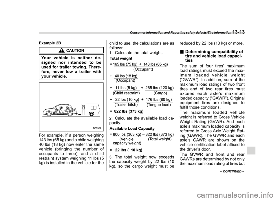
your vehicle.For example, if a person weighing
143 lbs (65 kg) and a child weighing
40 lbs (18 kg) now enter the same
vehicle (bringing the number of
occupants to three), and a child
restraint system weighing 11 lbs (5
kg) is installed in the vehicle for thechild to use, the calculations are as
follows:
1.
Calculate the total weight.
2.
Calculate the available load ca-
pacity.
3.
The total weight now exceeds
the capacity weight by 22 lbs (10
kg), so the cargo weight must bereduced by 22 lbs (10 kg) or more.
&Determining compatibility of
tire and vehicle load capaci-
tiesThe sum of four tires’maximum
load ratings must exceed the max-
imum loaded vehicle weight
(“GVWR”). In addition, sum of the
maximum load ratings of two front
tires and of two rear tires must
exceed each axle’s maximum
loaded capacity (“GAWR”). Original
equipment tires are designed to
fulfill those conditions.
The maximum loaded vehicle
weight is referred to Gross Vehicle
Weight Rating (GVWR). And each
axle’s maximum loaded capacity is
referred to Gross Axle Weight Rat-
ing (GAWR). The GVWR and each
axle’s GAWR are shown on the
vehicle certification label affixed to
the driver’s door.
The GVWR and front and rear
GAWRs are determined by not only
the maximum load rating of tires but
–CONTINUED–
Consumer information and Reporting safety defects/Tire information
13-13
13