2018 RENAULT MEGANE engine
[x] Cancel search: enginePage 268 of 348

4.16
BODYWORK MAINTENANCE (2/3)
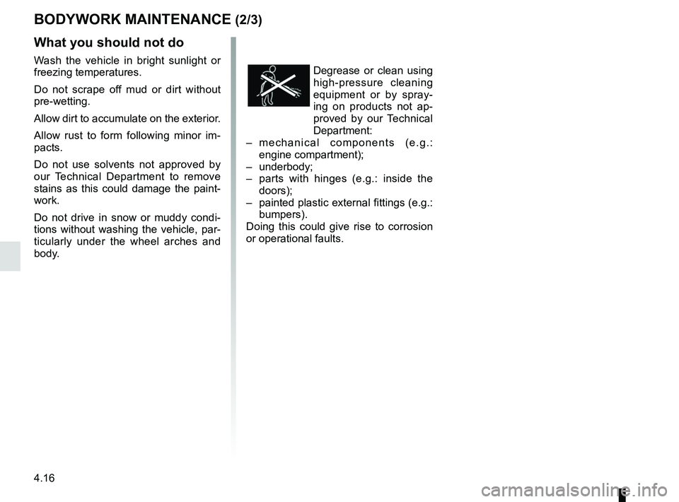
Degrease or clean using
high-pressure cleaning
equipment or by spray-
ing on products not ap-
proved by our Technical
Department:
– mechanical components (e.g.:
engine compartment);
– underbody;
– parts with hinges (e.g.: inside the
doors);
– painted plastic external fittings (e.g.:
bumpers).
Doing this could give rise to corrosion
or operational faults.
What you should not do
Wash the vehicle in bright sunlight or
freezing temperatures.
Do not scrape off mud or dirt without
pre-wetting.
Allow dirt to accumulate on the exterior.
Allow rust to form following minor im-
pacts.
Do not use solvents not approved by
our Technical Department to remove
stains as this could damage the paint-
work.
Do not drive in snow or muddy condi-
tions without washing the vehicle, par-
ticularly under the wheel arches and
body.
Page 277 of 348

5.5
TYRE PRESSURE KIT (2/3)
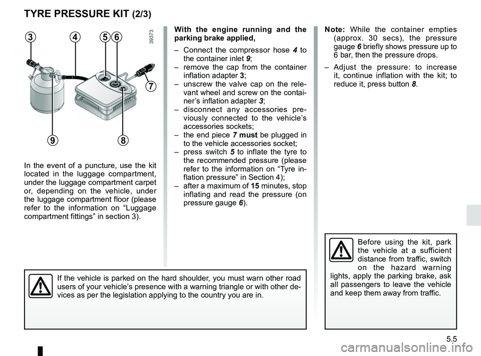
In the event of a puncture, use the kit
located in the luggage compartment,
under the luggage compartment carpet
or, depending on the vehicle, under
the luggage compartment floor (please
refer to the information on “Luggage
compartment fittings” in section 3).
Before using the kit, park
the vehicle at a sufficient
distance from traffic, switch
on the hazard warning
lights, apply the parking brake, ask
all passengers to leave the vehicle
and keep them away from traffic.
Note: While the container empties (approx. 30 secs), the pressure
gauge 6 briefly shows pressure up to
6 bar, then the pressure drops.
– Adjust the pressure: to increase it, continue inflation with the kit; to
reduce it, press button 8.
If the vehicle is parked on the hard shoulder, you must warn other road
users of your vehicle’s presence with a warning triangle or with other de-
vices as per the legislation applying to the country you are in.
With the engine running and the
parking brake applied,
– Connect the compressor hose 4 to
the container inlet 9;
– remove the cap from the container inflation adapter 3;
– unscrew the valve cap on the rele- vant wheel and screw on the contai-
ner’s inflation adapter 3;
– disconnect any accessories pre- viously connected to the vehicle’s
accessories sockets;
– the end piece 7 must be plugged in
to the vehicle accessories socket;
– press switch 5 to inflate the tyre to
the recommended pressure (please
refer to the information on “Tyre in-
flation pressure” in Section 4);
– after a maximum of 15 minutes, stop inflating and read the pressure (on
pressure gauge 6).563
9
7
4
8
Page 286 of 348

5.14
Any operation on (or modi-
fication to) the electrical
system must be performed
by an approved dealer
since an incorrect connection might
damage the electrical equipment
(harness, components and in partic-
ular the alternator). In addition, your
Dealer has all the parts required for
fitting these units.
LED dipped beam
headlights 1
Please see an authorised dealer.
LED main beam headlights 2
Please see an authorised dealer.
FRONT HEADLIGHTS: replacing the bulbs (1/2)
Halogen dipped beam
headlight
To change the bulb:
– open the bonnet;
– remove cover B;
– Turn the bulb holder a quarter turn 4;
– remove the bulb.
Bulb type: H7.
Once the bulb has been replaced,
check that it is properly secured.
BA
The bulbs are under pres-
sure and can break when
replaced.
Risk of injury.
1
Please note when work-
ing close to the engine that
it may be hot. In addition,
the engine cooling fan may
start at any moment. The
warning light in the engine compart-
ment reminds you of this.
Risk of injury.
2
Page 302 of 348

5.30
BATTERY: troubleshooting (1/2)
To avoid all risk of sparks:
– Ensure that any consumers (cour-tesy lights, etc.) are switched off
before disconnecting or reconnect-
ing the battery;
– when charging, stop the charger before connecting or disconnecting
the battery;
– to avoid creating a short circuit be- tween the terminals, do not place
metal objects on the battery;
– always wait at least one minute after the engine has been switched off
before disconnecting a battery;
– make sure that you reconnect the battery terminals after refitting.
Connecting a battery charger
The battery charger must be com-
patible with a battery with nominal
voltage of 12 volts.
Do not disconnect the battery when the
engine is running. Follow the instruc-
tions given by the manufacturer of
the battery charger you are using.
Special procedures may be
required to charge some
batteries. Contact your au-
thorised dealer.
Avoid all risk of sparks which may
cause an immediate explosion, and
charge the battery in a well venti-
lated area.
Risk of serious injury.
Handle the battery with care
as it contains sulphuric acid,
which must not come into
contact with eyes or skin. If
it does, wash the affected area with
plenty of cold water. If necessary,
consult a doctor.
Ensure that naked flames, red hot
objects and sparks do not come into
contact with the battery as there is a
risk of explosion. There is a risk of
explosion.
The engine may be hot when car-
rying out operations in close prox-
imity. In addition, the engine cooling
fan can come on at any moment.
Risk of injury.
Before performing any
action in the engine com-
partment, the ignition must
be switched off (please see
the information on “Starting, stop-
ping the engine” in Section 2).
Please note when work-
ing close to the engine that
it may be hot. The engine
cooling fan may also start
at any moment. The
warning
light in the engine compartment re-
minds you of this.
Risk of injury.
Page 303 of 348

5.31
Starting the vehicle using the
battery from another vehicle
If you have to use the battery from an-
other vehicle to start, obtain suitable
jump leads (with a large cross section)
from an approved dealer or, if you al-
ready have jump leads, ensure that
they are in perfect condition.
The two batteries must have an iden-
tical nominal voltage of 12 volts. The
battery supplying the current should
have a capacity (amp-hours, Ah) which
is at least the same as that of the dis-
charged battery.
Ensure that there is no risk of contact
between the two vehicles (risk of short
circuiting when the positive terminals
are connected) and that the discharged
battery is properly connected. Switch
off your vehicle ignition.
Start the engine of the vehicle supply-
ing the current and run it at a moderate
speed.
BATTERY: troubleshooting (2/2)
3
B
A
1
Lift the red cover on box 1 located
behind the battery.
Connect the positive cable A to sup-
port 3 (+) located under the box
cover 1, then to terminal 5 (+) of the
battery supplying the current.
Connect the negative cable B to termi-
nal 4 ( – ) of the battery supplying the
current then to the metal cable 2 ( – )
of the discharged battery.
2
54
Check that there is no con-
tact between leads A and B
and that the positive lead A
is not touching any metal
parts on the vehicle supplying the
current.
Risk of injury and/or damage to the
vehicle.
Start the engine, and as soon as it starts
running, disconnect cables A and B in
reverse order (2 - 4 - 5 - 3).
2
Page 307 of 348

5.35
WIPER BLADES: REPLACEMENT (1/2)
Replacing windscreen wiper
blades 1
With the ignition on and engine
switched off, lower the windscreen
wiper stalk completely: they stop
slightly away from the bonnet.
Lift wiper arm 3, pull tab 2 (move-
ment A) and push the blade upwards.
To refit
Slide the blade along the arm until it
clips on. Make sure that the blade is
correctly locked in position. Return the
windscreen wiper stalk to the park po-
sition.
1
2
3
Check the condition of the wiper
blades. You are responsible for their
service life:
– clean the blades, windscreen and rear screen regularly with soapy
water;
– do not use them when the wind- screen or rear screen are dry;
– free them from the windscreen or rear screen when they have not
been used for a long time.
A
– In frosty weather, make
sure that the wiper blades
are not stuck by ice (to
avoid the risk of the motor
overheating).
– Check the condition of the wiper
blades.
Replace the wiper blades as soon
as they begin to lose efficiency
(approximately once a year).
Whilst changing the blade, take care
not to drop the arm onto the window
after it has been removed as this
may break the window.
Page 309 of 348

5.37
TOWING: breakdown recovery (1/2)
Before towing, put the gearbox in neu-
tral, unlock the steering column and re-
lease the parking brake.
For vehicles fitted with an automatic
gearbox, if it is not possible to put the
gear lever into position N, please con-
sult an authorised dealer.
Steering column unlocking
Insert the key into the ignition or, de-
pending on the vehicle, having the
RENAULT card on you, press the
engine start button for 2 seconds.
Reposition the lever to neutral (posi-
tion N for vehicles fitted with an auto-
matic gearbox).
The column is unlocked, the acces-
sory functions are supplied: the vehi-
cle lights can be used (indicators, brake
lights etc.). At night the vehicle must
have its lights on.
Depending on the vehicle, once you
have finished towing, press the engine
start button twice (risk of running down
the battery). The speed specified by current legis-
lation for towing must always be ob-
served. If your vehicle is the towing
vehicle, do not exceed the maximum
towing weight for your vehicle (refer to
the information on “Weights” in Section
6).
Towing a vehicle with an
automatic gearbox
Transport the vehicle on a trailer or tow
it with the front wheels off the ground.
In exceptional circumstances
, you
may tow it with all four wheels on the
ground, only in a forward gear, with the
gear in neutral position N over a maxi-
mum distance of 50 miles and not ex-
ceeding a speed of 15 mph (25 km/h).
1
2
Do not remove the key from
the ignition when the vehi-
cle is being towed.
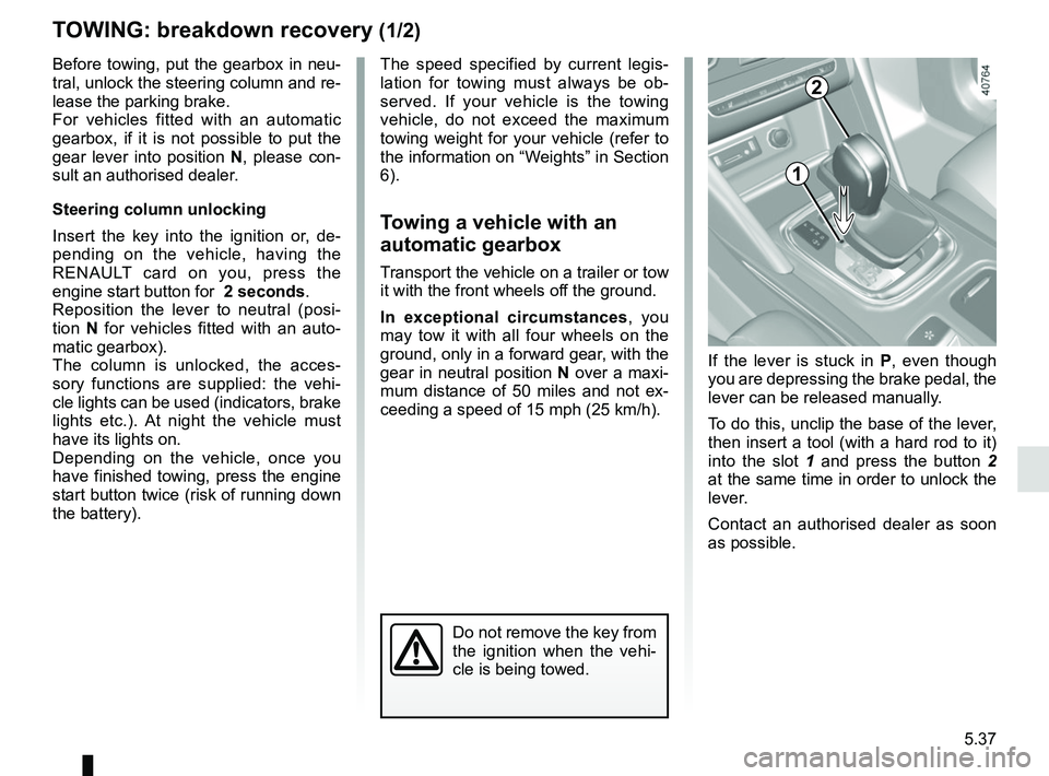
If the lever is stuck in P , even though
you are depressing the brake pedal, the
lever can be released manually.
To do this, unclip the base of the lever,
then insert a tool (with a hard rod to it)
into the slot 1 and press the button 2
at the same time in order to unlock the
lever.
Contact an authorised dealer as soon
as possible.
Page 311 of 348

5.39
OPERATING FAULTS (1/7)
The following advice will enable you to carry out quick, temporary repai\
rs. For safety reasons you should always contact
an approved Dealer as soon as possible.
Using the RENAULT cardPOSSIBLE CAUSES WHAT TO DO
The RENAULT card does not lock or
unlock the doors. Card battery is flat.
Replace the battery or have it replaced.
You can still lock/unlock and start your
vehicle (refer to the information on
“Locking/unlocking the doors” in Section 1
and “Starting/Stopping the engine” in
Section 2).
Use of appliances operating on the
same frequency as the card (mobile
phone, etc.). Stop using the equipment or use the in-
tegrated key (refer to the information on
“Locking, unlocking the opening elements”
in Section 1).
Vehicle located in a high electromag-
netic radiation zone.
Vehicle battery flat. Use the key integrated in the card (refer to
the information on “Locking, unlocking the
opening elements” in Section 1).
The vehicle is started. With the engine running, the card’s locking/
unlocking device is blocked. Turn off the ig-
nition.