2018 RENAULT MASTER ECU
[x] Cancel search: ECUPage 32 of 290
1.26
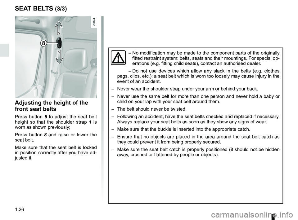
8
Adjusting the height of the
front seat belts
Press button 8 to adjust the seat belt
height so that the shoulder strap 1 is
worn as shown previously;
Press button 8 and raise or lower the
seat belt.
Make sure that the seat belt is locked
in position correctly after you have ad-
justed it.
SEAT BELTS (3/3)
– No modification may be made to the component parts of the originally
fitted restraint system: belts, seats and their mountings. For special o\
p-
erations (e.g. fitting child seats), contact an authorised dealer.
– Do not use devices which allow any slack in the belts (e.g. clothes
pegs, clips, etc.): a seat belt which is worn too loosely may cause inj\
ury in the
event of an accident.
– Never wear the shoulder strap under your arm or behind your back.
– Never use the same belt for more than one person and never hold a baby o\
r child on your lap with your seat belt around them.
– The belt should never be twisted.
– Following an accident, have the seat belts checked and replaced if neces\
sary. Always replace your seat belts as soon as they show any signs of wear.
– Make sure that the buckle is inserted into the appropriate catch.
– Ensure that no objects are placed in the area around the seat belt catch\
as they could prevent it from being properly secured.
– Make sure the seat belt catch is properly positioned (it should not be \
hidden away, crushed or flattened by people or objects).
Page 34 of 290
1.28
METHODS OF RESTRAINT IN ADDITION TO THE FRONT SEAT BELTS (1/3)
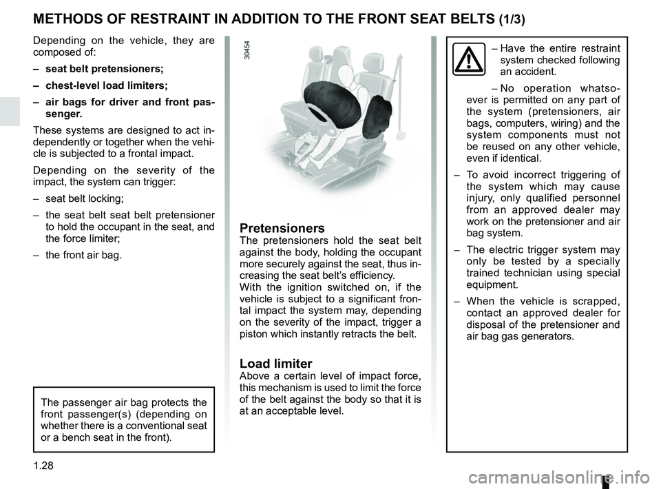
Depending on the vehicle, they are
composed of:
– seat belt pretensioners;
– chest-level load limiters;
– air bags for driver and front pas-senger.
These systems are designed to act in-
dependently or together when the vehi-
cle is subjected to a frontal impact.
Depending on the severity of the
impact, the system can trigger:
– seat belt locking;
– the seat belt seat belt pretensioner to hold the occupant in the seat, and
the force limiter;
– the front air bag.– Have the entire restraint
system checked following
an accident.
– No operation whatso-
ever is permitted on any part of
the system (pretensioners, air
bags, computers, wiring) and the
system components must not
be reused on any other vehicle,
even if identical.
– To avoid incorrect triggering of the system which may cause
injury, only qualified personnel
from an approved dealer may
work on the pretensioner and air
bag system.
– The electric trigger system may only be tested by a specially
trained technician using special
equipment.
– When the vehicle is scrapped, contact an approved dealer for
disposal of the pretensioner and
air bag gas generators.
The passenger air bag protects the
front passenger(s) (depending on
whether there is a conventional seat
or a bench seat in the front).
PretensionersThe pretensioners hold the seat belt
against the body, holding the occupant
more securely against the seat, thus in-
creasing the seat belt’s efficiency.
With the ignition switched on, if the
vehicle is subject to a significant fron-
tal impact the system may, depending
on the severity of the impact, trigger a
piston which instantly retracts the belt.
Load limiterAbove a certain level of impact force,
this mechanism is used to limit the force
of the belt against the body so that it is
at an acceptable level.
Page 195 of 290
3.29
TRANSPORTING OBJECTS (1/2)
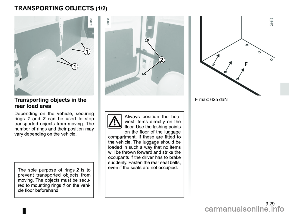
F max: 625 daN
Always position the hea-
viest items directly on the
floor. Use the lashing points
on the floor of the luggage
compartment, if these are fitted to
the vehicle. The luggage should be
loaded in such a way that no items
will be thrown forward and strike the
occupants if the driver has to brake
suddenly. Fasten the rear seat belts,
even if the seats are not occupied.
Transporting objects in the
rear load area
Depending on the vehicle, securing
rings 1 and 2 can be used to stop
transported objects from moving. The
number of rings and their position may
vary depending on the vehicle.
2
1
1
The sole purpose of rings 2 is to
prevent transported objects from
moving. The objects must be secu-
red to mounting rings 1 on the vehi-
cle floor beforehand.
Page 203 of 290

4.7
Filling: take care when
topping up the oil that
no oil drips onto engine
components - risk of fire.
Remember to refit the cap securely
as there is a risk of fire if oil splashes
onto hot engine components.
Engine oil change: if you
are changing the oil when
the engine is hot, be careful
not to scald yourself if the
oil overflows.
Never run the engine in an
enclosed space as exhaust
gases are poisonous.
ENGINE OIL LEVEL : topping up, filling (2/2)
Please note when work-
ing close to the engine that
it may be hot. In addition,
the engine cooling fan may
start at any moment. The
warning light in the engine compart-
ment reminds you of this.
Risk of injury.
Consult your approved Dealer at
once if you notice an abnormal or
repeated drop in any of the fluid
levels.
Before performing any
action in the engine com-
partment, the ignition must
be switched off (please see
the information on “Starting, stop-
ping the engine” in Section 2).
Exceeding the maximum
engine oil level
Under no circumstances
must the maximum fill level
be exceeded: risk of damage to the
engine and catalytic converter.
If the oil level exceeds the maximum
level, do not start your vehicle and
contact an approved Dealer.
When working in the engine
compartment, ensure that
the windscreen wiper stalk
is in the park position.
Risk of injury.
Page 212 of 290
4.16
Using a roller type car wash
Return the windscreen wiper stalk to
the Park position (refer to the informa-
tion on the “Windscreen washer, wiper”
in Section 1). Check the mounting of
external accessories, additional lights
and mirrors, and ensure that the wiper
blades are secured with adhesive tape.
Remove the radio aerial mast if your
vehicle is fitted with this equipment.
Remember to remove the tape and refit
the antenna after washing.
Vehicles with a matte paint
finish
This type of paint requires certain pre-
cautions.
You should do the following
Wash the vehicle by hand using plenty
of water, using a soft cloth or a gentle
sponge.
Do not do the following
Use wax-based products (polishing).
Rub too hard.
Wash the vehicle in a roller-type car
wash.
Attach stickers to the paintwork (risk of
leaving marks).
Wash the vehicle
using a high-pressure
cleaning device.
BODYWORK MAINTENANCE (3/3)Cleaning the headlights
As the headlights are made of plastic
“glass”, use a soft cloth or cotton wool
to clean them. If this does not clean
them properly, moisten the cloth with
soapy water, then wipe clean with a soft
damp cloth or cotton wool.
Finally, carefully dry off with a soft dry
cloth.
Do not use cleaning products con-
taining alcohol or utensils (e.g.: a
scraper).
Page 217 of 290
5.3
PUNCTURE, EMERGENCY SPARE WHEEL (2/2)
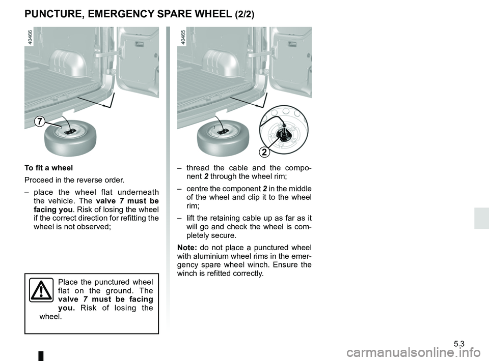
– thread the cable and the compo-nent 2 through the wheel rim;
– centre the component 2 in the middle
of the wheel and clip it to the wheel
rim;
– lift the retaining cable up as far as it will go and check the wheel is com-
pletely secure.
Note: do not place a punctured wheel
with aluminium wheel rims in the emer-
gency spare wheel winch. Ensure the
winch is refitted correctly.
To fit a wheel
Proceed in the reverse order.
– place the wheel flat underneath
the vehicle. The valve 7 must be
facing you . Risk of losing the wheel
if the correct direction for refitting the
wheel is not observed;
7
Place the punctured wheel
flat on the ground. The
valve 7 must be facing
you. Risk of losing the
wheel.
2
Page 218 of 290
5.4
TOOL KIT
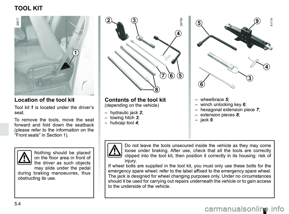
Location of the tool kit
Tool kit 1 is located under the driver’s
seat.
To remove the tools, move the seat
forward and fold down the seatback
(please refer to the information on the
“Front seats” in Section 1).
Contents of the tool kit(depending on the vehicle)
– hydraulic jack 2;
– towing hitch 3;
– hubcap tool 4;
1
Do not leave the tools unsecured inside the vehicle as they may come
loose under braking. After use, check that all the tools are correctly
clipped into the tool kit, then position it correctly in its housing: ri\
sk of
injury.
If wheel bolts are supplied in the tool kit, you must only use these bol\
ts for the
emergency spare wheel: refer to the label affixed to the emergency spare wheel.
The jack is designed for wheel changing purposes only. Under no circumstances
should it be used for carrying out repairs underneath the vehicle or to \
gain access
to the underside of the vehicle.
Nothing should be placed
on the floor area in front of
the driver as such objects
may slide under the pedal
during braking manoeuvres, thus
obstructing its use.
23
4
56
– wheelbrace 5;
– winch unlocking key 6;
– hexagonal extension piece 7;
– extension pieces 8;
– jack 9.
59
4
3
6
7
8
Page 222 of 290

5.8
TYRE INFLATION KIT (4/6)
Affix the driving recommendation label
to the dashboard where it can easily be
seen by the driver;
Store the kit underneath the driver’s
seat.
Start the vehicle immediately in order
to the distribute the product in the tyre
and, after 6 miles (10 km) or 10 min-
utes driving, stop to check the pres-
sure. To do this, fit adapter 3 onto the
tyre valve. If the pressure is less than
the recommended pressure, adjust it
(refer to the information on “Tyre pres-
sures”), otherwise contact an approved
dealer: repair is not possible.Precautions when using the
kit
– the kit should not be operated for more than 15 consecutive minutes;
– when driving, vibration may be felt due to the presence of the repair
product injected into the tyre.
Following repair with the kit,
do not travel further than
120 miles (200 km). In addi-
tion, reduce your speed and
under no circumstances exceed
48 mph (80 km/h). The sticker,
which you must affix in a prominent
position on the dashboard, reminds
you of this.
Depending on the country or local
legislation, a tyre repaired with the
inflation kit may need to be replaced.
3
Please be aware that a poorly tightened or missing valve cap can make
the tyres less airtight and lead to pressure loss.
Always use valve caps identical to those fitted originally and tighten t\
hem
fully.
Nothing should be placed
around the driver’s feet
as such objects may slide
under the pedals during
sudden braking manoeuvres and
obstruct their use.
Once the tyre is correctly inflated,
remove the kit: slowly unscrew the in-
flation adapter 3 to prevent any prod-
uct spatter and screw the tyre inflation
hose 4 to the bottle opening 2 to pre-
vent the product from escaping.
4
2