2018 Ram ProMaster clock
[x] Cancel search: clockPage 50 of 337

IconDescription
Temperature Control
Use this control to regulate the temperature of the air inside the passenger compartment. Rotat-
ing the knob counterclockwise, from top center into the blue area of the scale, indicates cooler
temperatures. Rotating the knob clockwise, into the red area, indicates warmer temperatures.
Blower Control
There are seven blower speeds. Use this control to regulate the amount of air forced through the
system in any mode you select. The blower speed increases as you move the control clockwise
from the OFF position.
NOTE:Depending on the configuration, your vehicle may be equipped with four blower
speeds.
Modes Control
Turn the knob to change the airflow distribution mode. The airflow distribution mode can be
adjusted so air comes from the instrument panel outlets, floor outlets, defrost outlets and demist
outlets. The Mode settings are as follows:
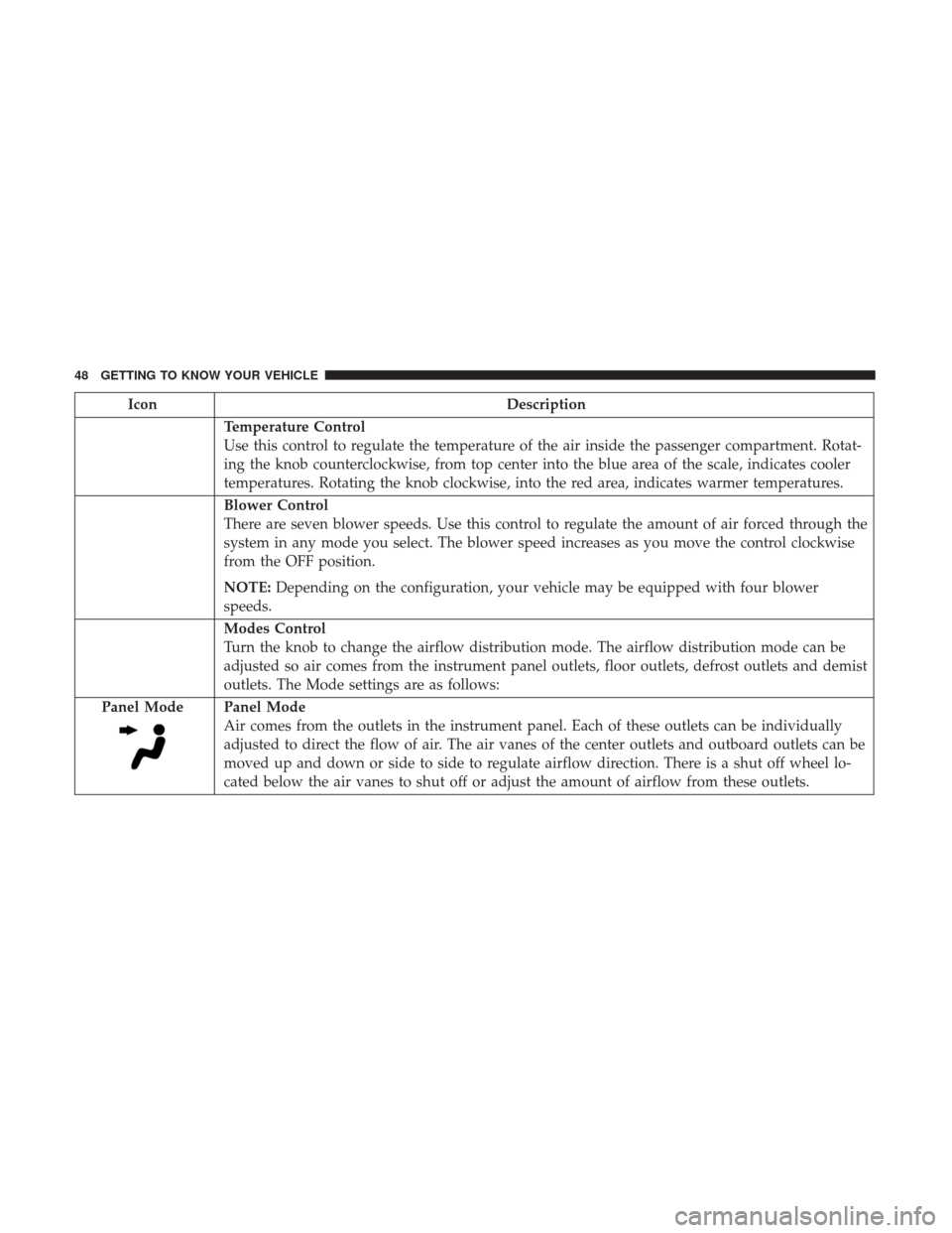
Panel Mode
Panel Mode
Air comes from the outlets in the instrument panel. Each of these outlets can be individually
adjusted to direct the flow of air. The air vanes of the center outlets and outboard outlets can be
moved up and down or side to side to regulate airflow direction. There is a shut off wheel lo-
cated below the air vanes to shut off or adjust the amount of airflow from these outlets.
48 GETTING TO KNOW YOUR VEHICLE
Page 73 of 337

The setup menu can be activated by pushing theMODE
button. Single pushes on the upordown arrow button will
scroll through the setup menu options. The menu items
include the following functions:
• Speed Beep
• Buzzer Volume
• Seat Belt Buzzer (Just Available After SBR Disable Made
By CHR Service)
• Service (Diesel Only)
• Exit menu
NOTE:
• If equipped, some customer programmable features
will display in the Uconnect system. Refer to your
Uconnect Owner ’s Manual Supplement for further
information.
• The clock setting procedure can be done through the
radio or the instrument cluster display.
Selecting An Option Of The Main Menu Without Submenu
1. Briefly push and release the MODEbutton to select the
main menu option to set. 2. Push and release the
upordown arrow button (by
single pushes) to select the new setting.
3. Briefly push and release the MODEbutton to store the
new setting and go back to the main menu option
previously selected.
Selecting An Option Of The Main Menu With Submenu
1. Briefly push and release the MODEbutton to display
the first submenu option.
2. Push and release the upordown arrow button (by
single pushes) to scroll through all the submenu options.
3. Briefly push and release the MODEbutton to select the
displayed submenu option and to open the relevant
setup menu.
4. Push and release the upordown arrow button (by
single pushes) to select the new setting for this submenu
option.
5. Briefly push and release the MODEbutton to store the
new setting and go back to the previously selected
submenu option.
6. Push and release and hold the MODEbutton to return
to the main menu (short hold) or the main screen (longer
hold).
4
GETTING TO KNOW YOUR INSTRUMENT PANEL 71
Page 75 of 337

NOTE:
•If equipped, some customer programmable features
will display in the Uconnect system. Refer to
“Uconnect Settings” in “Multimedia” for further infor-
mation.
• The instrument cluster display clock setting and
Uconnect clock setting procedure can be done through
the radio or the instrument cluster display.
TRIP COMPUTER
The Trip Computer is located in the instrument cluster. It
features a driver-interactive display (displays information
such as trip information, range, fuel consumption, average
speed, and travel time).
Trip Button
The TRIP button, located on the right steering column
stalk, can be used to display and to reset the previously
described values.
• A short button push displays the different values.
• A long button push resets the system and then starts a
new trip. New Trip
To reset:
•
Push and hold the TRIP button to reset the system
manually.
• When the “Trip distance” reaches 99999.9 miles or
kilometers or when the “Travel time” reaches 999.59 (999
hours and 59 minutes), the system is reset automatically.
• Disconnecting/Reconnecting the battery resets the sys-
tem.
NOTE: If the reset operation occurs in the presence of the
screens concerning Trip A or Trip B, only the information
associated with Trip A or Trip B functions will be reset.
Start Of Trip Procedure
With the ignition on, push and hold the TRIP button for
over two seconds to reset trip information.
Exit Trip
1. To exit the Trip function, wait until all the values have been displayed or hold the MENU button for longer
than one second.
4
GETTING TO KNOW YOUR INSTRUMENT PANEL 73
Page 183 of 337

Replacing Exterior Bulbs
Headlamps Low Beam And High beam
NOTE:Passenger side headlamp must be removed for
bulb replacement, for driver side headlamp go to step 6
through step 12.
1. Remove one screw on the lower headlamp filler panel.
2. Remove two screws on the upper headlamp filler panel.
3. Remove one upper screw from the headlamp housing.
4. Remove two lower screws from the headlamp housing.
5. Pull Headlamp forward.
6. Remove appropriate plastic cap from the back of the headlamp housing.
7. Push down on the upper portion of the socket.
8. Pull the socket outward from reflector.
9. Pull bulb outward from socket.
10. Install new bulb.
11. Push socket back into reflector until it locks back into place. 12. Install access cap.
13. Carefully reinstall headlamp in the same position on
the vehicle, so as not to affect headlamp aiming.
14. Install one upper screw on the headlamp housing.
15. Install two lower screws on the headlamp housing.
16. Carefully reinstall one screw on the lower headlamp filler panel.
17. Carefully reinstall two screws on the upper headlamp filler panel.
Front Turn Signal/Parking Lamps
NOTE: Passenger side headlamp must be removed for
bulb replacement, for driver side headlamp go to step 6
through step 7.
1. Remove one screw on the lower headlamp filler panel.
2. Remove two screws on the upper headlamp filler panel.
3. Remove one upper screw from the headlamp housing.
4. Remove two lower screws from the headlamp housing.
5. Pull Headlamp forward.
6. Rotate the bulb counter clockwise and remove.
7
IN CASE OF EMERGENCY 181
Page 184 of 337

7. Install the bulb into socket, and rotate bulb/socketclockwise into lamp locking it in place.
8. Carefully reinstall headlamp in the same position on the vehicle, so as not to affect headlamp aiming.
9. Install the one upper screw on headlamp housing.
10. Install the two lower screws on headlamp housing.
11. Carefully reinstall one screw on the lower headlamp filler panel.
12. Carefully reinstall two screws the on upper headlamp filler panel.
Daytime Running Lamp (DRL)/Front Side Marker
Lamp
NOTE: Passenger side headlamp must be removed for
bulb replacement, for driver side headlamp go to step 6
through step 8.
1. Remove one screw on the lower headlamp filler panel.
2. Remove two screws on the upper headlamp filler panel.
3. Remove one upper screw from the headlamp housing.
4. Remove two lower screws from the headlamp housing. 5. Pull Headlamp forward.
6. Remove the DRL, side marker bulb by pulling straight
out.
7. Replace lamp as required and lock in place.
8. Reinstall plastic cap.
9. Carefully reinstall headlamp in the same position on the vehicle, as not to affect headlamp aiming.
10. Install the one upper screw on the headlamp housing.
11. Install the two lower screws on the headlamp housing.
12. Carefully reinstall one screw on the lower headlamp filler panel.
13. Carefully reinstall two screws on the upper headlamp filler panel.
Front Fog Lamps
1. Turn front wheels inboard to access cover in wheel liner.
2. Open the cover on the front of the wheel liner.
3. Remove connection and replace the bulb.
4. Connect the wire and rotate bulb/socket clockwise intolamp locking it in place.
182 IN CASE OF EMERGENCY
Page 185 of 337

5. Reinstall the plastic cap and close the cover on the wheelliner.
Front, Rear Roof Lamps
1. Remove two screw and remove the lamp assembly.
2. Remove the socket bulb by turning counterclockwise.
3. Remove bulb and replace as needed.
4. Reinstall the bulb socket and rotate clockwise to lock inplace.
5. Reinstall lamp.
Rear Tail, Stop, Backup, Turn Signal And Rear Side
Marker Lamps
1. Open rear doors.
2. Remove the two screws and remove the tail lamp.
3. Remove the tail/stop, turn signal, backup and rear side marker bulb/socket by rotating counter-clockwise.
4. Remove the bulb and replace as needed.
5. Reinstall bulb/socket and rotate clockwise to lock in place.
6. Reinstall lamp.
Replacing Interior Bulbs
Cargo Lamp
1. Using a suitable tool, remove either the lamp above the back door or the sliding door lamp as needed and
disconnect it.
Rear Cargo Lamp Bulb Access
7
IN CASE OF EMERGENCY 183
Page 197 of 337

JACKING AND TIRE CHANGING
WARNING!
•Do not attempt to change a tire on the side of the
vehicle close to moving traffic. Pull far enough off
the road to avoid the danger of being hit when
operating the jack or changing the wheel.
• Being under a jacked-up vehicle is dangerous. The
vehicle could slip off the jack and fall on you. You
could be crushed. Never put any part of your body
under a vehicle that is on a jack. If you need to get
under a raised vehicle, take it to a service center
where it can be raised on a lift.
• Never start or run the engine while the vehicle is on
a jack.
• The jack is designed to be used as a tool for changing
tires only. The jack should not be used to lift the
vehicle for service purposes. The vehicle should be
jacked on a firm level surface only. Avoid ice or
slippery areas.
Jack Location
The jack and jack tools are stored under the front passenger
seat.
To release the jack kit for it’s storage location, you must
push down and turn the lock knob 1/4 turn counter
clockwise to the unlock position.
Jack Kit Location
7
IN CASE OF EMERGENCY 195
Page 200 of 337

The winch mechanism is located under the rear of the
vehicle to the right of the spare tire.2. Rotate the wheel wrench handle counterclockwise until
the spare tire is on the ground with enough cable slack
to allow you to pull it out from under the vehicle.
NOTE: The winch mechanism is designed for use with the
winch extension tube only. Use of an air wrench or other
power tools is not recommended and can damage the
winch.
Winch LocationWinch Extension
198 IN CASE OF EMERGENCY