2018 Ram 2500 def
[x] Cancel search: defPage 90 of 372

AUXILIARY DRIVING SYSTEMS
Tire Pressure Monitoring System
(TPMS)
The Tire Pressure Monitor System (TPMS)
will warn the driver of a low tire pressure
based on the vehicle recommended cold
placard pressure.
The tire pressure will vary with temperature
by about 1 psi (7 kPa) for every 12°F (6.5°C).
This means that when the outside tempera-
ture decreases, the tire pressure will de-
crease. Tire pressure should always be set
based on cold inflation tire pressure. This is
defined as the tire pressure after the vehicle
has not been driven for at least three hours, or
driven less than 1 mile (1.6 km) after a three
hour period. The cold tire inflation pressure
must not exceed the maximum inflation pres-
sure molded into the tire sidewall. Refer to
“Tires” in “Servicing And Maintenance” for
information on how to properly inflate the
vehicle’s tires. The tire pressure will also
increase as the vehicle is driven - this is
normal and there should be no adjustment for
this increased pressure.The TPMS will warn the driver of a low tire
pressure if the tire pressure falls below the
low-pressure warning limit for any reason,
including low temperature effects and natu-
ral pressure loss through the tire.
The TPMS will continue to warn the driver of
low tire pressure as long as the condition
exists, and will not turn off until the tire
pressure is at or above the recommended
cold placard pressure. Once the low tire pres-
sure warning (Tire Pressure Monitoring [TPM]
Telltale Light) illuminates, you must increase
the tire pressure to the recommended cold
placard pressure in order for the TPM Telltale
Light to turn off. The system will automati-
cally update and the TPM Telltale Light will
turn off once the system receives the updated
tire pressures. The vehicle may need to be
driven for up to 20 minutes above 15 mph
(24 km/h) in order for the TPMS to receive
this information.
NOTE:
When filling warm tires, the tire pressure may
need to be increased up to an additional 4 psi
(30 kPa) above the recommended cold plac-
ard pressure in order to turn the Tire Pressure
Monitoring Telltale Light off.
For example, your vehicle may have a recom-
mended cold (parked for more than three
hours) placard pressure of 30 psi (207 kPa).
If the ambient temperature is 68°F (20°C)
and the measured tire pressure is 27 psi
(186 kPa), a temperature drop to 20°F (-7°C)
will decrease the tire pressure to approxi-
mately 23 psi (158 kPa). This tire pressure is
sufficiently low enough to turn on the TPM
Telltale Light. Driving the vehicle may cause
the tire pressure to rise to approximately
27 psi (186 kPa), but the TPM Telltale Light
will still be on. In this situation, the TPM
Telltale Light will turn off only after the tires
are inflated to the vehicle’s recommended
cold placard pressure value.
SAFETY
88
Page 109 of 372
Because air bag sensors measure vehicle de-
celeration over time, vehicle speed and dam-
age by themselves are not good indicators of
whether or not an air bag should have de-
ployed.
Seat belts are necessary for your protection in
all collisions, and also are needed to help
keep you in position, away from an inflating
air bag.
When the ORC detects a collision requiring
the front air bags, it signals the inflator units.
A large quantity of non-toxic gas is generated
to inflate the front air bags.
The steering wheel hub trim cover and the
upper right side of the instrument panel
separate and fold out of the way as the air
bags inflate to their full size. The front air
bags fully inflate in less time than it takes to
blink your eyes. The front air bags then
quickly deflate while helping to restrain the
driver and front passenger.Knee Impact Bolsters
The Knee Impact Bolsters help protect the
knees of the driver and front passenger, and
position the front occupants for improved
interaction with the front air bags.
WARNING!
• Do not drill, cut, or tamper with the kneeimpact bolsters in any way.
• Do not mount any accessories to the
knee impact bolsters such as alarm
lights, stereos, citizen band radios, etc.
Supplemental Side Air Bags
Ram 1500
Supplemental Seat-Mounted Side Air Bags
(SABs)
This vehicle is equipped with Supplemental
Seat-Mounted Side Air Bags (SABs).
Supplemental Seat-Mounted Side Air Bags
(SABs) are located in the outboard side of the
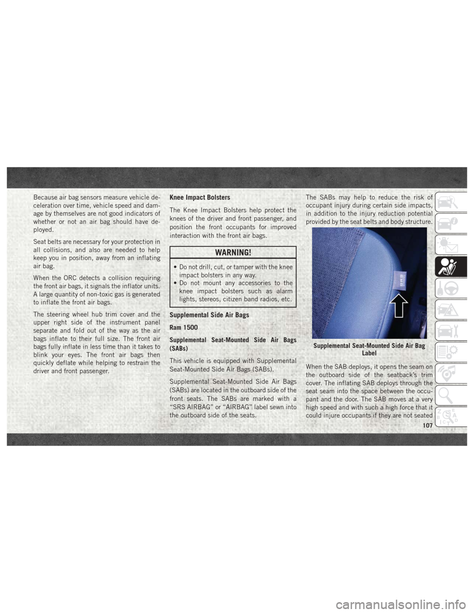
front seats. The SABs are marked with a
“SRS AIRBAG” or “AIRBAG” label sewn into
the outboard side of the seats. The SABs may help to reduce the risk of
occupant injury during certain side impacts,
in addition to the injury reduction potential
provided by the seat belts and body structure.
When the SAB deploys, it opens the seam on
the outboard side of the seatback’s trim
cover. The inflating SAB deploys through the
seat seam into the space between the occu-
pant and the door. The SAB moves at a very
high speed and with such a high force that it
could injure occupants if they are not seated
Supplemental Seat-Mounted Side Air Bag
Label
107
Page 115 of 372

Rollover Events (If Equipped With Rollover
Sensing)
Side Air Bags are designed to activate in
certain rollover events. The Occupant Re-
straint Controller (ORC) determines whether
the deployment of the Side Air Bags in a
particular rollover event is appropriate, based
on the severity and type of collision. Vehicle
damage by itself is not a good indicator of
whether or not Side Air Bags should have
deployed.
The Side Air Bags will not deploy in all
rollover events. The rollover sensing-system
determines if a rollover event may be in
progress and whether deployment is appro-
priate. A slower-developing event may deploy
the seat belt pretensioners on both sides of
the vehicle. A faster-developing event may
deploy the seat belt pretensioners as well as
the Side Air Bags on both sides of the vehicle.
The rollover sensing-system may also deploy
the seat belt pretensioners, with or without
the Side Air Bags, on both sides of the vehicle
if the vehicle experiences a near rollover
event.The SABICs may help reduce the risk of
partial or complete ejection of vehicle occu-
pants through side windows in certain roll-
over or side impact events.
Air Bag System Components
NOTE:
The Occupant Restraint Controller (ORC)
monitors the internal circuits and intercon-
necting wiring associated with electrical Air
Bag System Components listed below:
• Occupant Restraint Controller (ORC)
• Air Bag Warning Light
• Steering Wheel and Column
• Instrument Panel
• Knee Impact Bolsters
• Driver and Front Passenger Air Bags
• Seat Belt Buckle Switch
• Supplemental Side Air Bags
• Front and Side Impact Sensors — If
Equipped
• Seat Belt Pretensioners
If A Deployment Occurs
The front air bags are designed to deflate
immediately after deployment.
NOTE:
Front and/or side air bags will not deploy in all
collisions. This does not mean something is
wrong with the air bag system.
If you do have a collision which deploys the
air bags, any or all of the following may occur:
• The air bag material may sometimes cause abrasions and/or skin reddening to the oc-
cupants as the air bags deploy and unfold.
The abrasions are similar to friction rope
burns or those you might get sliding along a
carpet or gymnasium floor. They are not
caused by contact with chemicals. They are
not permanent and normally heal quickly.
However, if you haven’t healed significantly
within a few days, or if you have any blis-
tering, see your doctor immediately.
• As the air bags deflate, you may see some smoke-like particles. The particles are a
normal by-product of the process that gen-
erates the non-toxic gas used for air bag
inflation. These airborne particles may irri-
tate the skin, eyes, nose, or throat. If you
113
Page 137 of 372

Front seat belt assemblies must be replaced
after a collision. Rear seat belt assemblies
must be replaced after a collision if they have
been damaged (i.e., bent retractor, torn web-
bing, etc.). If there is any question regarding
seat belt or retractor condition, replace the
seat belt.
Air Bag Warning Light
The Air Bag warning lightwill turn on for
four to eight seconds as a bulb check when
the ignition switch is first turned to ON/RUN.
If the light is either not on during starting,
stays on, or turns on while driving, have the
system inspected at your authorized dealer as
soon as possible. After the bulb check, this
light will illuminate with a single chime when
a fault with the Air Bag System has been
detected. It will stay on until the fault is
cleared. If the light comes on intermittently
or remains on while driving, have your autho-
rized dealer service the vehicle immediately.
Refer to “Occupant Restraint Systems” in
“Safety” for further information.
Defroster
Check operation by selecting the defrost
mode and place the blower control on high
speed. You should be able to feel the air
directed against the windshield. See your
authorized dealer for service if your defroster
is inoperable.
Floor Mat Safety Information
Always use floor mats designed to fit your
vehicle. Only use a floor mat that does not
interfere with the operation of the accelera-
tor, brake or clutch pedals. Only use a floor
mat that is securely attached using the floor
mat fasteners so it cannot slip out of position
and interfere with the accelerator, brake or
clutch pedals or impair safe operation of your
vehicle in other ways.
WARNING!
An improperly attached, damaged, folded,
or stacked floor mat, or damaged floor mat
fasteners may cause your floor mat to in-
terfere with the accelerator, brake, or
clutch pedals and cause a loss of vehicle
control. To prevent SERIOUS INJURY or
DEATH:
• ALWAYS securely attach
your floor
mat using the floor mat fasteners. DO
NOT install your floor mat upside down
or turn your floor mat over. Lightly pull to
confirm mat is secured using the floor
mat fasteners on a regular basis.
• ALWAYS REMOVE THE EXISTING
FLOOR MAT FROM THE VEHICLE
before installing any other floor mat.
NEVER install or stack an additional
floor mat on top of an existing floor mat.
• ONLY install floor mats designed to fit
your vehicle. NEVER install a floor mat
that cannot be properly attached and
secured to your vehicle. If a floor mat
needs to be replaced, only use a FCA
approved floor mat for the specific
make, model, and year of your vehicle.
135
Page 143 of 372

• Ignition switched from RUN to ACC
NOTE:
For Keyless Go equipped vehicles, The en-
gine will turn off and the ignition switch will
change to ACC mode. After 30 minutes the
ignition switches to OFF automatically, un-
less the driver turns the ignition switch OFF.
If the vehicle is not in PARK and the driver exits
the vehicle with the engine running, the vehicle
may AutoPark.
AutoPark will engage when all of these con-
ditions are met:
• Vehicle is equipped with a rotary shifter andan 8-speed transmission
• Vehicle is not in PARK
• Vehicle speed is 1.2 MPH (1.9 km/h) or less
• Driver’s seat belt is unbuckled
• Driver’s door is ajar
• Brake Pedal is not depressed
The MESSAGE “AutoPark Engaged Shift to P
then Shift to Gear” will display in the instru-
ment cluster. NOTE:
In some cases the ParkSense graphic will be
displayed in the instrument cluster, causing
the “AutoPark Engaged Shift to P then Shift to
Gear” to not be seen. In these cases, the
shifter must be returned to “P” to select
desired gear.
If the driver shifts into PARK while moving, the
vehicle may AutoPark.
AutoPark will engage
ONLYwhen vehicle
speed is 1.2 MPH (1.9 km/h) or less.
The MESSAGE “Vehicle Speed is Too High to
Shift to P”will be displayed in the instrument
cluster if vehicle speed is above 1.2 MPH
(1.9 km/h).
WARNING!
If vehicle speed is above 1.2 MPH
(1.9 km/h), the transmission will default to
NEUTRAL until the vehicle speed drops
below 1.2 MPH (1.9 km). A vehicle left in
the NEUTRAL position can roll. As an
added precaution, always apply the park-
ing brake when exiting the vehicle. 4WD LOW — If Equipped
AutoPark will be disabled when operating the
vehicle in 4WD LOW.
The MESSAGE “AutoPark Disabled” will be
displayed in the instrument cluster.
Additional customer warnings will be given
when all of these conditions are met:
• Vehicle is not in PARK
• Driver’s Door is ajar
• Vehicle is in 4WD LOW range
The MESSAGE “AutoPark Not Engaged” will
be displayed in the instrument cluster. A
warning chime will continue until you shift
the vehicle into PARK or the Driver’s Door is
closed.
ALWAYS DO A VISUAL CHECK that your vehicle
is in PARK by looking for the "P" in the
Instrument Cluster Display and near the
shifter. As an added precaution, always apply
the parking brake when exiting the vehicle.
141
Page 147 of 372

• Vehicle is not in PARK
• Vehicle speed is 1.2 MPH (1.9 km/h) orless
• Driver’s seat belt is unbuckled
• Driver’s door is ajar
• Brake Pedal is not depressed
The MESSAGE “AutoPark Engaged Shift to P
then Shift to Gear” will display in the instru-
ment cluster.
NOTE:
In some cases the ParkSense graphic will be
displayed in the instrument cluster, causing
the “AutoPark Engaged Shift to P then Shift to
Gear” to not be seen. In these cases, the
shifter must be returned to “P” to select
desired gear.
If the driver shifts into PARK while moving, the
vehicle may AutoPark.
AutoPark will engage ONLYwhen vehicle
speed is 1.2 MPH (1.9 km/h) or less.
The MESSAGE “Vehicle Speed is Too High to
Shift to P”will be displayed in the instrument
cluster if vehicle speed is above 1.2 MPH
(1.9 km/h).WARNING!
If vehicle speed is above 1.2 MPH
(1.9 km/h), the transmission will default to
NEUTRAL until the vehicle speed drops
below 1.2 MPH (1.9 km). A vehicle left in
the NEUTRAL position can roll. As an
added precaution, always apply the park-
ing brake when exiting the vehicle.
4WD LOW — If Equipped
AutoPark will be disabled when operating the
vehicle in 4WD LOW.
The MESSAGE “AutoPark Disabled” will be
displayed in the instrument cluster.
Additional customer warnings will be given
when all of these conditions are met:
• Vehicle is not in PARK
• Driver’s Door is ajar
• Vehicle is in 4WD LOW range
The MESSAGE “AutoPark Not Engaged” will
be displayed in the instrument cluster. A
warning chime will continue until you shift
the vehicle into PARK or the Driver’s Door is
closed. ALWAYS DO A VISUAL CHECK
that your vehicle
is in PARK by looking for the "P" in the
Instrument Cluster Display and near the
shifter. As an added precaution, always apply
the parking brake when exiting the vehicle.
Extreme Cold Weather
The engine block heater is a resistance heater
installed in the water jacket of the engine. It
requires a 110–115 Volt AC electrical outlet
with a grounded, three-wire extension cord.
Its use is recommended for environments
that routinely fall below -10°F (-23°C). It
should be used when the vehicle has not been
running overnight or longer periods and
should be plugged in two hours prior to start.
Its use is required for cold starts with tem-
peratures under -20°F (-28°C).
NOTE:
The engine block heater cord is a factory
installed option. If your vehicle is not
equipped, heater cords are available from
your authorized Mopar dealer.
• A 12 Volt heater built into the fuel filter housing aids in preventing fuel gelling. It is
controlled by a built-in thermostat.
145
Page 184 of 372

Materials Added To Fuel
Designated TOP TIER
Detergent Gasoline
contains a higher level
of detergents to fur-
ther aide in minimiz-
ing engine and fuel
system deposits. When
available, the usage of
Top Tier Detergent gasoline is recommended.
Visit www.toptiergas.com for a list of TOP
TIER Detergent Gasoline Retailers.
Indiscriminate use of fuel system cleaning
agents should be avoided. Many of these
materials intended for gum and varnish re-
moval may contain active solvents or similar
ingredients. These can harm fuel system gas-
ket and diaphragm materials.
REFUELING THE VEHICLE—
1500 DIESEL MODELS
1. Open the fuel filler door.NOTE:
There is no fuel filler cap. A flapper door
inside the filler pipe seals the system. 2. Insert the fuel nozzle fully into the filler
pipe – the nozzle opens and holds the
flapper door while refueling.
3. Fill the vehicle with fuel – when the fuel nozzle “clicks” or shuts off the fuel tank is
full.
4. Remove the fuel nozzle and close the fuel door.
Emergency Fuel Can Refueling
Most fuel cans will not open the flapper door.
A funnel is provided to open the flapper door
to allow emergency refueling with a fuel can.
1. Retrieve fuel funnel from the jack kit located under the front passenger seat.
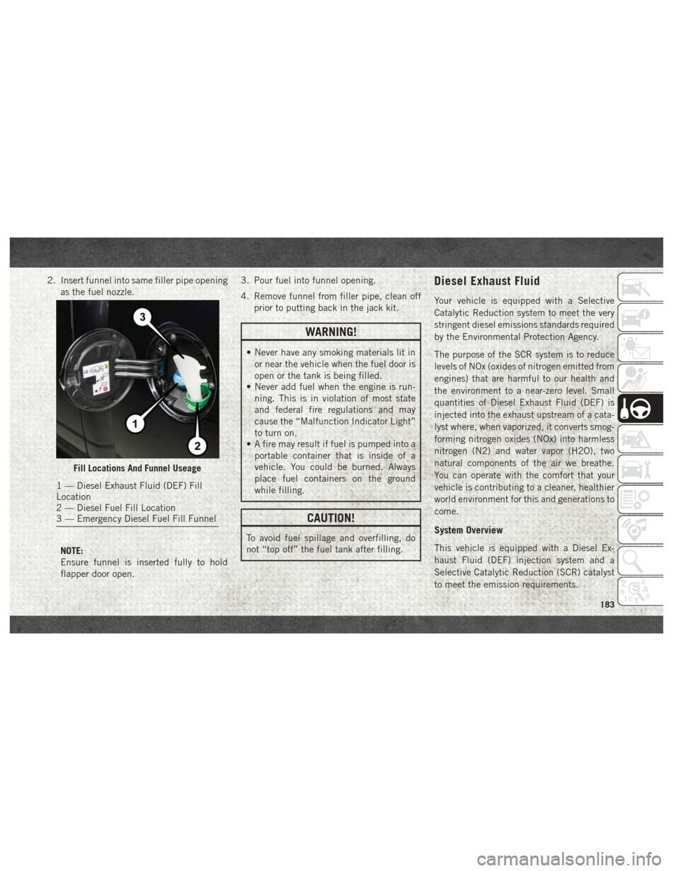
Fill Locations
1 — Diesel Exhaust Fluid (DEF) Fill
Location
2 — Diesel Fuel Fill Location
STARTING AND OPERATING
182
Page 185 of 372
2. Insert funnel into same filler pipe openingas the fuel nozzle.
NOTE:
Ensure funnel is inserted fully to hold
flapper door open. 3. Pour fuel into funnel opening.
4. Remove funnel from filler pipe, clean off
prior to putting back in the jack kit.
WARNING!
• Never have any smoking materials lit inor near the vehicle when the fuel door is
open or the tank is being filled.
• Never add fuel when the engine is run-
ning. This is in violation of most state
and federal fire regulations and may
cause the “Malfunction Indicator Light”
to turn on.
• A fire may result if fuel is pumped into a
portable container that is inside of a
vehicle. You could be burned. Always
place fuel containers on the ground
while filling.
CAUTION!
To avoid fuel spillage and overfilling, do
not “top off” the fuel tank after filling.
Diesel Exhaust Fluid
Your vehicle is equipped with a Selective
Catalytic Reduction system to meet the very
stringent diesel emissions standards required
by the Environmental Protection Agency.
The purpose of the SCR system is to reduce
levels of NOx (oxides of nitrogen emitted from
engines) that are harmful to our health and
the environment to a near-zero level. Small
quantities of Diesel Exhaust Fluid (DEF) is
injected into the exhaust upstream of a cata-
lyst where, when vaporized, it converts smog-
forming nitrogen oxides (NOx) into harmless
nitrogen (N2) and water vapor (H2O), two
natural components of the air we breathe.
You can operate with the comfort that your
vehicle is contributing to a cleaner, healthier
world environment for this and generations to
come.
System Overview
This vehicle is equipped with a Diesel Ex-
haust Fluid (DEF) injection system and a
Selective Catalytic Reduction (SCR) catalyst
to meet the emission requirements.
Fill Locations And Funnel Useage
1 — Diesel Exhaust Fluid (DEF) Fill
Location
2 — Diesel Fuel Fill Location
3 — Emergency Diesel Fuel Fill Funnel
183