Page 440 of 702
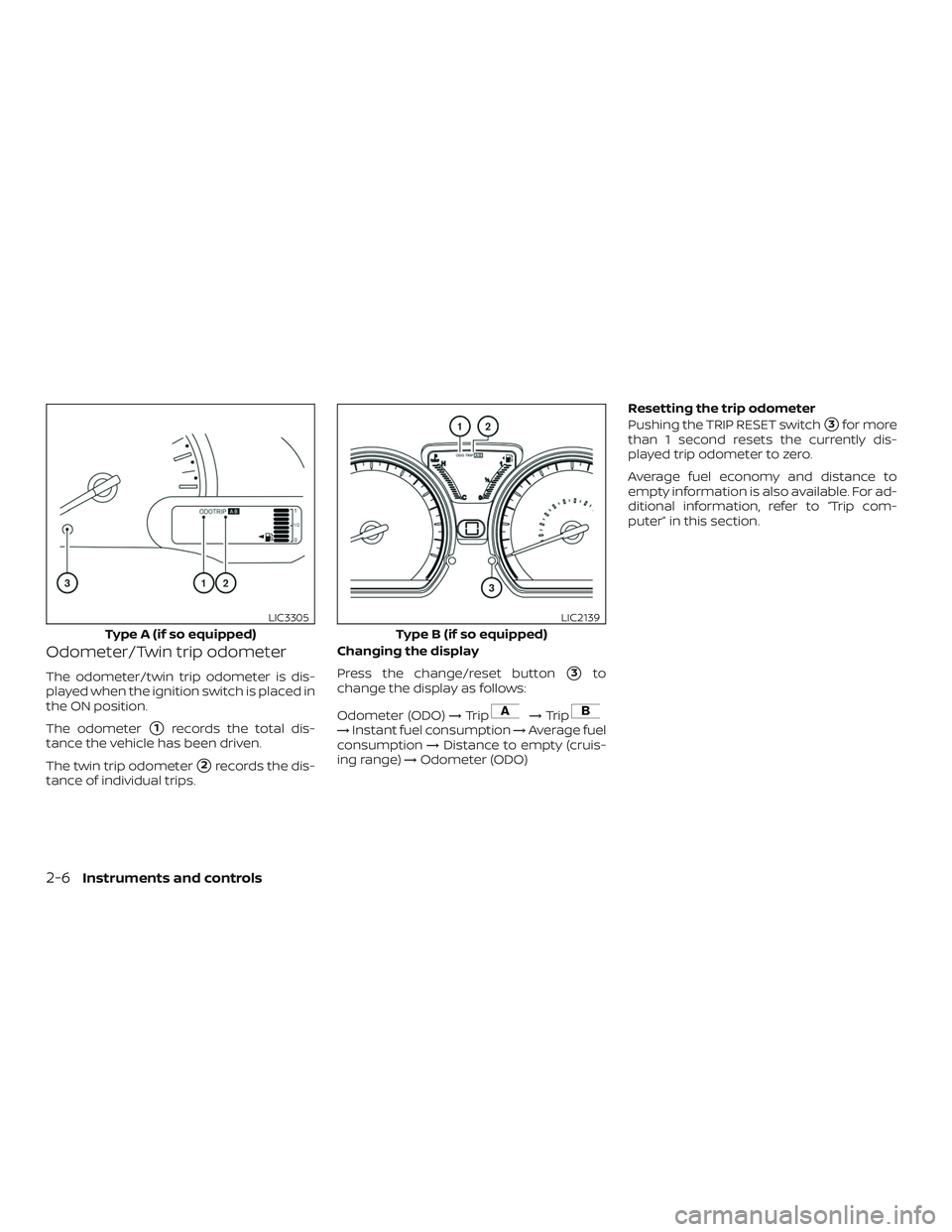
Odometer/Twin trip odometer
The odometer/twin trip odometer is dis-
played when the ignition switch is placed in
the ON position.
The odometer
�1records the total dis-
tance the vehicle has been driven.
The twin trip odometer
�2records the dis-
tance of individual trips. Changing the display
Press the change/reset button
�3to
change the display as follows:
Odometer (ODO) →Trip
→Trip→Instant fuel consumption →Average fuel
consumption →Distance to empty (cruis-
ing range) →Odometer (ODO) Resetting the trip odometer
Pushing the TRIP RESET switch
�3for more
than 1 second resets the currently dis-
played trip odometer to zero.
Average fuel economy and distance to
empty information is also available. For ad-
ditional information, refer to “Trip com-
puter” in this section.
Type A (if so equipped)
LIC3305
Type B (if so equipped)
LIC2139
2-6Instruments and controls
Page 441 of 702
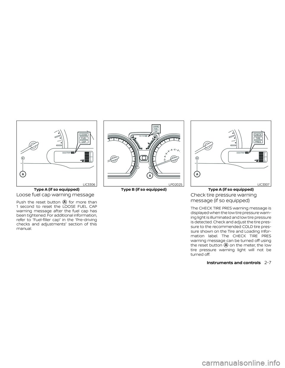
Loose fuel cap warning message
Push the reset button�Afor more than
1 second to reset the LOOSE FUEL CAP
warning message af ter the fuel cap has
been tightened. For additional information,
refer to “Fuel-filler cap” in the “Pre-driving
checks and adjustments” section of this
manual.
Check tire pressure warning
message (if so equipped)
The CHECK TIRE PRES warning message is
displayed when the low tire pressure warn-
ing light is illuminated and low tire pressure
is detected. Check and adjust the tire pres-
sure to the recommended COLD tire pres-
sure shown on the Tire and Loading Infor-
mation label. The CHECK TIRE PRES
warning message can be turned off using
the reset button
�Aon the meter, the low
tire pressure warning light will not be
turned off.
Type A (if so equipped)
LIC3306
Type B (if so equipped)
LPD2025
Type A (if so equipped)
LIC3307
Instruments and controls2-7
Page 443 of 702

Type A (if so equipped)
Engine coolant temperature monitoring is
performed by the high temperature warn-
ing light. For additional information, refer")
ENGINE COOLANT TEMPERATURE
GAUGE (if so equipped)
Type A (if so equipped)
Engine coolant temperature monitoring is
performed by the high temperature warn-
ing light. For additional information, refer to
“High temperature warning light” in this
section.Type B (if so equipped)
NOTE:
The ignition switch must be placed in the
ON position for the gauge to give a read-
ing.
The gauge indicates the engine coolant
temperature. The engine coolant tempera-
ture will vary with the outside air tempera-
ture and driving conditions.
CAUTION
If the gauge indicates a coolant tem-
perature near the hot (H) end of the nor-
mal range, reduce vehicle speed to de-
crease the temperature. If the gauge is
over the normal range, stop the vehicle
as soon as safely possible. If the engine
is overheated, continued operation of
the vehicle may seriously damage the
engine. For additional information, re-
fer to “If your vehicle overheats” in the
“In case of emergency ” section of this
manual for immediate action required.
FUEL GAUGE
The gauge indicates the
approximatefuel
level in the tank when the ignition switch is
placed in the ON position.
The gauge may move slightly during brak-
ing, turning, acceleration, or going up or
down hills.
Type A (if so equipped): The fuel level seg-
ments
�Awill blink when the amount of fuel
in the tank is getting low.
Type B (if so equipped)
LIC2501
Type A (if so equipped)
LIC2286
Instruments and controls2-9
Page 444 of 702
:The low fuel warn-
ing light
�Awill turn on when the amount of
fuel in the tank is getting low.
Refill the fuel tank before the gauge reg-
isters 0 (Empty).
The
indicates that")
Type B (if so equipped):The low fuel warn-
ing light
�Awill turn on when the amount of
fuel in the tank is getting low.
Refill the fuel tank before the gauge reg-
isters 0 (Empty).
The
indicates that the fuel-filler
door is located on the driver’s side of the
vehicle.
CAUTION
∙ If the vehicle runs out of fuel, thecheck engine light may come on. Re-
fuel as soon as possible. Af ter a few
driving trips, the
light should
turn off. If the light remains on af ter a
few driving trips, have the vehicle in-
spected. It is recommended that you
visit a NISSAN dealer for this service.
∙ For additional information, refer to “Malfunction Indicator Light (MIL)” in
this section.
TRIP COMPUTER
When the ignition switch is placed in the ON
position, modes of the trip computer can
be selected by pushing the change/reset
button
�Aon the instrument panel located
near the speedometer. The following
modes can be selected in the display
�B:
∙ Odometer
∙ Trip A
∙ Trip B
Type B (if so equipped)
LIC2287
Type A (if so equipped)
LIC2470
2-10Instruments and controls
Page 445 of 702

Odometer
The odometer records the total distance
the vehicle has been drive")
∙ Instant fuel consumption
∙ Average fuel consumption
∙ Distance to empty
∙ Outside air temperature (if so equipped)
Odometer
The odometer records the total distance
the vehicle has been driven.
Trip A
Measures the distance of one specific trip.
Trip B
Measures the distance of a second specific
trip.
Instant fuel consumption
The instant fuel consumption mode shows
the instant fuel economy. The display up-
dates instantly when driving.
Average fuel consumption (mpg
or l (liter)/100 km)
The average fuel consumption mode
shows the average fuel consumption since
the last reset. Resetting is done by pressing
the trip or change button for more than
approximately 1 second. The display is up-
dated every 30 seconds. At about the first
1/3 mi (500 m) af ter a reset, the display
shows (----).
Distance to empty
The distance to empty mode provides you
with an estimation of the distance that can
be driven before refueling. The range is
constantly being calculated, based on the
amount of fuel in the fuel tank and the
actual fuel consumption.The distance to empty includes a low
range warning feature: when the fuel level
is low, the distance to empty is automati-
cally selected and the digits blink in order
to draw the driver’s attention. Press the trip
computer change/reset button
�Aif you
wish to return to the mode that was se-
lected before the warning occurred.
When the fuel level drops even lower, the
distance to empty will display (----).
Outside air temperature (°F or °C)
(if so equipped)
The outside air temperature is displayed in
°F or °C.
The ambient temperature sensor is lo-
cated in front of the radiator. The sensor
may be affected by road or engine heat,
wind directions and other driving condi-
tions. The display may differ from the ac-
tual ambient temperature or the tempera-
ture displayed on various signs or
billboards.
Trip computer reset
Pressing the change/reset button for
more than 3 seconds will reset all modes
except Trip A and distance to empty.
Type B (if so equipped)
LIC2138
Instruments and controls2-11
Page 482 of 702

OPENER OPERATION
The fuel-filler door release is located below
the instrument panel. To open the fuel-filler
door, pull the release. To lock, close the fuel-
filler door securely.
FUEL-FILLER CAP
WARNING
∙ Gasoline is extremely flammable andhighly explosive under certain condi-
tions. You could be burned or seri-
ously injured if it is misused or mis-
handled. Always stop the engine and
do not smoke or allow open flames or
sparks near the vehicle when
refueling. ∙ Do not attempt to top off the fuel tank
af ter the fuel pump nozzle shuts off
automatically. Continued refueling
may cause fuel overflow, resulting in
fuel spray and possibly a fire.
∙ Use only an original equipment type fuel-filler cap as a replacement. It has
a built-in safety valve needed for
proper operation of the fuel system
and emission control system. An in-
correct cap can result in a serious mal-
function and possible injury. It could
also cause the
Malfunction Indi-
cator Light (MIL) to come on.
∙ Never pour fuel into the throttle body to attempt to start your vehicle.
∙ Do not fill a portable fuel container in the vehicle or trailer. Static electricity
can cause an explosion of flammable
liquid, vapor or gas in any vehicle or
trailer. To reduce the risk of serious
injury or death when filling portable
fuel containers:
– Always place the container on the ground when filling.
– Do not use electronic devices when filling.
LPD2805LPD2616
FUEL-FILLER DOOR
3-14Pre-driving checks and adjustments
Page 484 of 702

LOOSE FUEL CAP warning
message
The LOOSE FUEL CAP warning message
displays in the trip computer when the
fuel-filler cap is not tightened correctly af-
ter the vehicle has been refueled. It may
take a few driving trips for the message to
be displayed. To turn off the warning mes-
sage, perform the following:1. Remove and install the fuel-filler cap as previously described as soon as pos-
sible.
2. Tighten the fuel-filler cap until it clicks. 3. Press the loose fuel cap warning reset
button
�Ain the meter for about 1 sec-
ond to turn off the LOOSE FUEL CAP
warning message af ter tightening the
fuel-filler cap.
TILT OPERATION
Push the lock lever�1down and adjust the
steering wheel up or down
�2to the de-
sired position.
Pull the lock lever
�1up to lock the steering
wheel in place.
WARNING
Do not adjust the steering wheel while
driving. You could lose control of your
vehicle and cause an accident.
Type A (if so equipped)
LPD2025
Type B (if so equipped)
LPD2343LPD2674
STEERING WHEEL
3-16Pre-driving checks and adjustments
Page 626 of 702

∙ Never pour fuel into the throttle bodyor attempt to start the engine with
the air cleaner removed. Doing so
could result in serious injury.
To remove the filter from the air cleaner,
release the retaining clips
�A, then release
the holders at the back of the unit. Pull the
unit upward
�B.
The viscous paper type filter element (if so
equipped) should not be cleaned and re-
used. The dry paper type filter element (if so
equipped) may be cleaned and reused. Re-
place the air filter according to the mainte-
nance log shown in the “Maintenance and
schedules” section of this manual.
When replacing the air filter, wipe the inside
of the air cleaner housing and the cover
with a damp cloth.
NOTE:
Af ter installing a new air cleaner filter,
make sure the air cleaner cover is seated
in the housing and latch the clips
�A.
CLEANING
If your windshield is not clear af ter using
the windshield–washer or if a wiper blade
chatters when running, wax or other mate-
rial may be on the blade or windshield.
Clean the outside of the windshield with a
washer fluid or a mild detergent. Your wind-
shield is clean if beads do not form when
rinsing with clear water.
Clean each blade by wiping it with a cloth
soaked in a washer fluid or a mild deter-
gent. Then rinse the blades with clear wa-
ter. If your windshield is still not clear af ter
cleaning the blades and using the wiper,
install new windshield wiper blades.
CAUTION
Worn windshield wiper blades can
damage the windshield and impair
driver vision.
REPLACING
Replace the wiper blades if they are worn.
1. Lif t the wiper arm away from the wind- shield.
2. Push and hold the release tab
�A, and
then move the wiper blade down
�B
the wiper arm to remove.
3. Remove the wiper blade.
4. Insert the new wiper blade onto the wiper arm until it clicks into place.
LDI2725
WINDSHIELD WIPER BLADES
8-16Do-it-yourself