Page 90 of 507

are similar to those of a higher severity
impact. They are designed to inflate on the
side where the vehicle is impacted. They
may not inflate in certain side collisions.
Curtain air bags are also designed to inflate
in certain types of rollover collisions or near
rollovers. As a result, certain vehicle move-
ments (for example, during severe off-
roading) may cause the curtain air bags to
inflate.
Vehicle damage (or lack of it) is not always
an indication of proper side air bag and
curtain air bag operation.
When the side air bags and curtain air bags
inflate, a fairly loud noise may be heard,
followed by release of smoke. This smoke is
not harmful and does not indicate a fire.
Care should be taken not to inhale it, as it
may cause irritation and choking. Those
with a history of a breathing condition
should get fresh air promptly.
Side air bags, along with the use of seat
belts, help to cushion the impact force on
the chest and pelvic area of the front occu-
pants. Curtain air bags help to cushion the
impact force to the head of occupants in
the front and rear outboard seating posi-
tions. They can help save lives and reduce
serious injuries. However, an inflating sideair bag and curtain air bag may cause
abrasions or other injuries. Side air bags
and curtain air bags do not provide re-
straint to the lower body.
The seat belts should be correctly worn
and the driver and passenger seated up-
right as far as practical away from the side
air bag. Rear seat passengers should be
seated as far away as practical from the
door finishers and side roof rails. The side
air bags and curtain air bags inflate quickly
in order to help protect the front and rear
outboard occupants. Because of this, the
force of the side air bag and curtain air bag
inflating can increase the risk of injury if the
occupant is too close to, or is against, these
air bag modules during inflation. The side
air bag and will deflate quickly af ter the
collision is over.
The curtain air bag will remain inflated for a
short time.
The side air bags and curtain air bags
operate only when the ignition switch is
placed in the ON position.
Af ter placing the ignition switch in the
ON position, the supplemental air bag
warning light illuminates. The supple-
mental air bag warning light will turn off
af ter about 7 seconds if the system is
operational.
WARNING
∙ Do not place any objects near the
seatback of the front seats. Also, do
not place any objects (an umbrella,
bag, etc.) between the front door fin-
isher and the front seat. Such objects
may become dangerous projectiles
and cause injury if a side air bag
inflates.
∙ Right af ter inflation, several side air bag and curtain air bag system com-
ponents will be hot. Do not touch
them; you may severely burn yourself.
∙ No unauthorized changes should be made to any components or wiring of
the side air bag and curtain air bag
systems. This is to prevent damage to
or accidental inflation of the side air
bag and curtain air bag or damage to
the side air bag and curtain air bag
systems.
1-60Safety—Seats, seat belts and supplemental restraint system
Page 93 of 507

SUPPLEMENTAL AIR BAG WARNING
LIGHT
The supplemental air bag warning light,
displaying
in the instrument panel,
monitors the circuits for the air bag sys-
tems, pretensioner(s) and all related wiring.
When the ignition switch is placed in the ON
position, the supplemental air bag warning
light illuminates for about 7 seconds and
then turns off. This means the system is
operational. If any of the following conditions occur, the
front air bag, side air bag, curtain air bag
and pretensioner systems need servicing:
∙ The supplemental air bag warning light remains on af ter approximately 7 sec-
onds.
∙ The supplemental air bag warning light flashes intermittently.
∙ The supplemental air bag warning light does not come on at all.
Under these conditions, the front air bag,
side air bag, curtain air bag or pretensioner
systems may not operate properly. They
must be checked and repaired. It is recom-
mended that you visit a NISSAN dealer for
this service.WARNING
If the supplemental air bag warning
light is on, it could mean that the front
air bag, side air bag, curtain air bag
and/or pretensioner systems will not
operate in an accident. To help avoid
injury to yourself or others, have your
vehicle checked as soon as possible. It is
recommended that you visit a NISSAN
dealer for this service. NOTE:
In the event of a crash involving an air
bag deployment (side, front or both), the
vehicle’s hazard lamps (turn indicators)
will turn ON automatically.
Repair and replacement
procedure
The front air bags, side air bags, curtain air
bags and pretensioner(s) are designed to
inflate on a one-time-only basis. As a re-
minder, unless it is damaged, the supple-
mental air bag warning light remains illu-
minated af ter inflation has occurred. These
systems should be repaired and/or re-
placed as soon as possible. It is recom-
mended that you visit a NISSAN dealer for
this service.
When maintenance work is required on the
vehicle, the front air bags, side air bags,
curtain air bags, pretensioner(s) and re-
lated parts should be pointed out to the
person performing the maintenance. The
ignition switch should always be placed in
the LOCK position when working under the
hood or inside the vehicle.
LRS0100
Safety—Seats, seat belts and supplemental restraint system1-63
Page 99 of 507

11. Front passenger supplemental airbag (P. 1-44)
12. Glove box (P. 2-50)
13. Shif t lever (P. 5-17)
14. Climate controls (P. 4-23, 4-31)
15. Ignition switch (if so equipped)
(P. 5-9)
Push-button ignition switch
(if so equipped) (P. 5-11)
16. Tilt/Telescopic steering (P. 3-30)
17. Hood release (P. 3-25) Fuel filler door release (P. 3-27)
18. ECO mode switch (if so equipped)
(P. 5-26)
Vehicle Dynamic Control (VDC) OFF
switch (P. 2-48)
SPORT mode switch
(if so equipped) (P. 5-26)
19. Instrument brightness control
(P. 2-41)
Power mirror switch (P. 3-32)
Trunk release (P. 3-26)
* Refer to the separate NissanConnect®
Owner’s Manual (if so equipped).
Refer to the page number indicated in
parentheses for operating details.
1. Tachometer
2. Coolant temperature gauge
3. Warning and indicator lights
4. Fuel gauge
5. Speedometer 6. Odometer
Twin trip odometer
Trip computer
Fuel Economy
ECO mode indicator (if so equipped)
Outside temperature display
Type A (if so equipped)
LIC3415
METERS AND GAUGES
Instruments and controls2-3
Page 101 of 507
Speedometer
The speedometer indicates the vehicle
speed.Odometer/Twin trip odometer
The odometer�2and the twin trip odom-
eter
�1are displayed when the ignition
switch is placed in the ON position.
The odometer records the total distance
the vehicle has been driven.
The twin trip odometer records the dis-
tance of individual trips. Changing the display
Press thebutton on the steering
wheel to change the display as follows:
Accel guide/Average fuel economy →In-
stant fuel economy/Average fuel economy
→ Average fuel economy →Average speed
→ Distance to empty →Trip A →Trip B
LIC2255
Type A (if so equipped)
LIC3050
Type B (if so equipped)
LIC3526
Instruments and controls2-5
Page 103 of 507

The low tire pressure warning light remains
illuminated until the tires are inflated to the
recommended COLD tire pressure. The
CHECK TIRE PRES warning message is dis-
played each time the ignition switch is
placed in the ON position as long as the low
tire pressure warning light remains illumi-
nated. For additional information, refer to
“Low tire pressure warning light” in the “In-
struments and controls” section, “Tire Pres-
sure Monitoring System (TPMS)” in the
“Starting and driving” section, and “Wheels
and tires” in the “Do-it-yourself ” section of
this manual.
TACHOMETER
The tachometer indicates engine speed in
revolutions per minute (rpm).
Do not rev the engine into the red zone
�1.
CAUTION
When engine speed approaches the red
zone, shif t to a higher gear or reduce
engine speed. Operating the engine in
the red zone may cause serious engine
damage.
ENGINE COOLANT TEMPERATURE
GAUGE
NOTE:
The ignition switch must be placed in the
ON position for the gauge to give a read-
ing.
The gauge indicates the engine coolant
temperature. The engine coolant tempera-
ture is within the normal range when the
reading is within the zone
�Ashown in the
illustration.
LIC2219
Type A (if so equipped)
LIC2414
Instruments and controls2-7
Page 104 of 507
The engine coolant temperature varies
with the outside air temperature and driv-
ing conditions.
CAUTION
If the gauge indicates a coolant tem-
perature near the hot (H) end of the nor-
mal range, reduce vehicle speed to de-
crease the temperature. If the gauge is
over the normal range, stop the vehicle
as soon as safely possible. If the engine
is overheated, continued operation of
the vehicle may seriously damage the
engine. For additional information, re-
fer to “If your vehicle overheats” in the
“In case of emergency ” section for im-
mediate action required.
FUEL GAUGE
NOTE:
The ignition switch must be placed in the
ON position for the gauge to give a read-
ing.
The gauge indicates theapproximatefuel
level in the tank.
The gauge may move slightly during brak-
ing, turning, acceleration, or going up or
down hills.
Type B (if so equipped)
LIC3427
Type A (if so equipped)
LIC2445
2-8Instruments and controls
Page 105 of 507

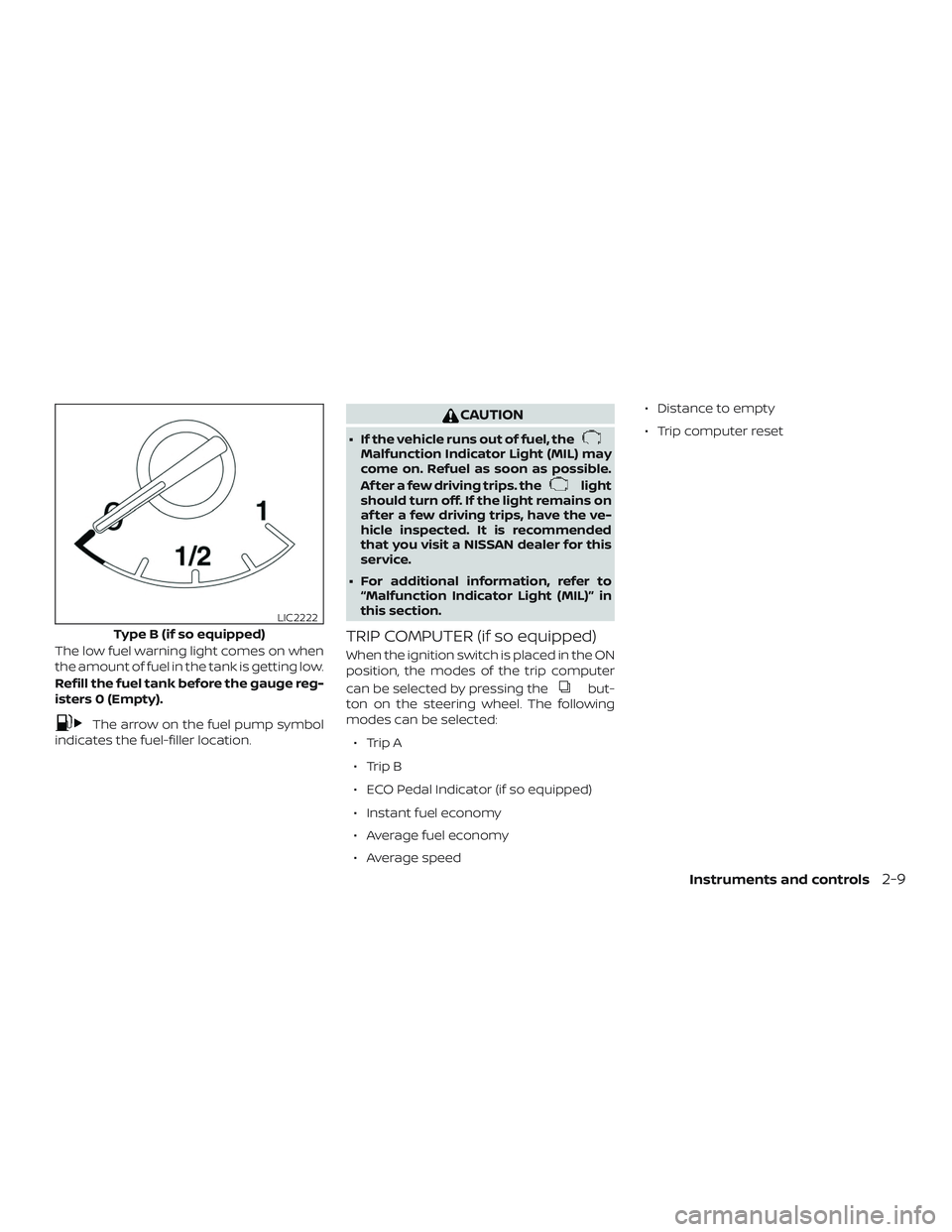
The low fuel warning light comes on when
the amount of fuel in the tank is getting low.
Refill the fuel tank before the gauge reg-
isters 0 (Empty).
The arrow on the fuel pump symbol
indicates the fuel-filler location.
CAUTION
∙ If the vehicle runs out of fuel, theMalfunction Indicator Light (MIL) may
come on. Refuel as soon as possible.
Af ter a few driving trips. the
light
should turn off. If the light remains on
af ter a few driving trips, have the ve-
hicle inspected. It is recommended
that you visit a NISSAN dealer for this
service.
∙ For additional information, refer to “Malfunction Indicator Light (MIL)” in
this section.
TRIP COMPUTER (if so equipped)
When the ignition switch is placed in the ON
position, the modes of the trip computer
can be selected by pressing the
but-
ton on the steering wheel. The following
modes can be selected:
∙ Trip A
∙ Trip B
∙ ECO Pedal Indicator (if so equipped)
∙ Instant fuel economy
∙ Average fuel economy
∙ Average speed ∙ Distance to empty
∙ Trip computer reset
Type B (if so equipped)
LIC2222
Instruments and controls2-9
Page 108 of 507
NOTE:
When driving uphill or rounding curves,
the fuel in the tank shif ts, which may
momentarily change the display.
Trip computer reset
To reset Trip A, Trip B, AVG/mpg, or
AVG/mph, go to the desired mode on the
trip computer and hold the
button on
the steering wheel for more than 3 sec-
onds.
OUTSIDE TEMPERATURE DISPLAY
The outside temperature function pro-
vides a display of the outside temperature
when the ignition switch is placed in the ON
position.
The display of positive temperatures is un-
signed (blank), negative temperatures are
prefixed with a minus sign.
The outside temperature will always be vis-
ible on the lef t side of the display.
LIC3149
2-12Instruments and controls