2018 NISSAN ROGUE SPORT fuel
[x] Cancel search: fuelPage 129 of 512

2-52Instruments and controls
SIC4544
The vehicle should be driven with the
Vehicle Dynamic Control (VDC) system on
for most driving conditions.
If the vehicle is stuck in mud or snow, the
VDC system reduces the engine output to
reduce wheel spin. The engine speed will
be reduced even if the accelerator is
depressed to the floor. If maximum en-
gine power is needed to free a stuck
vehicle, turn the VDC system off.
To turn off the VDC system, push the VDC
OFF switch. The
indicator light will
illuminate.
Push the VDC OFF switch again or restart the
engine to turn on the system. (See “Vehicle
Dynamic Control (VDC) system” (P.5-108).)
JVI1595X
The Intelligent 4x4 LOCK switch is located
on the instrument panel. The AWD LOCK
indicator light will illuminate when the
switch is turned on. For additional infor-
mation, refer to “Intelligent 4x4” (P.5-100).
Each time you push the switch, the AWD
mode will switch: AUTO ?LOCK ?AUTO.
JVS0185X
The ECO mode system helps to enhance
the fuel economy by controlling the
engine and CVT operation (for CVT mod-
els) automatically to avoid rapid accelera-
tion.
To turn on the ECO mode system, push
the ECO switch. The ECO mode indicator
appears on the meter.
To turn off the ECO mode, push the ECO
switch again. The ECO mode indicator will
turn off.
. The ECO mode system cannot be
turned off while the accelerator pedal
is depressed even if the ECO switch is
pushed to OFF. Release the accelera-
tor pedal to turn off the ECO mode
VEHICLE DYNAMIC CONTROL (VDC)
OFF SWITCH INTELLIGENT 4X4 LOCK SWITCH (if
so equipped)
ECO MODE SWITCH
Page 146 of 512

3 Pre-driving checks and adjustments
Keys ........................................................................\
................................. 3-2NISSAN Vehicle Immobilizer System key (if
so equipped) ........................................................................\
...... 3-2
Intelligent Key (if so equipped) ................................... 3-3
Doors ........................................................................\
.............................. 3-5 Locking with key .................................................................... 3-5
Locking with inside lock knob ..................................... 3-6
Locking with power door lock switch ................... 3-7
Automatic door locks ......................................................... 3-7
Child safety rear door lock ............................................. 3-7
Remote keyless entry system (if so equipped) ...... 3-8 How to use remote keyless entry system ......... 3-9
Intelligent Key system (if so equipped) .................... 3-11
Intelligent Key operating range .............................. 3-13
Door locks/unlocks precaution ............................... 3-13
Intelligent Key operation .............................................. 3-14
Battery saver system ....................................................... 3-16
Warning lights and audible reminders .............. 3-16
Troubleshooting guide ................................................... 3-17
How to use remote keyless entry function ...... 3-18 Remote engine start (if so equipped) ...................... 3-22
Remote engine start operating range ............ 3-22
Remote starting the engine .................................... 3-22
Extending engine run time ....................................... 3-23
Canceling a remote start ........................................... 3-23
Conditions the remote engine start will
not work ........................................................................\
.......... 3-23
Hood ........................................................................\
............................ 3-24
Liftgate ........................................................................\
...................... 3-25 Liftgate release lever ..................................................... 3-26
Fuel-filler door ........................................................................\
..... 3-27 Opening the fuel-filler door ...................................... 3-27
Fuel-filler cap ....................................................................... 3-27
Tilt/telescopic steering ........................................................ 3-29 Tilt or telescopic operation ...................................... 3-30
Sun visors ........................................................................\
................ 3-30
Mirrors ........................................................................\
...................... 3-31 Inside mirror ........................................................................\
. 3-31
Outside mirrors .................................................................. 3-31
Vanity mirror ........................................................................\
3-33
Page 172 of 512
WARNING
.Fuel is extremely flammable and
highly explosive under certain
conditions. You could be burned
or seriously injured if it is misused
or mishandled. Always stop the
engine and do not smoke or allow
open flames or sparks near the
vehicle when refueling.
. Fuel may be under pressure. Turn
the cap a half of a turn, and wait
for any “hissing” sound to stop to
prevent fuel from spraying out
and possibly causing personal
injury. Then remove the cap.
. Use only an original equipment
type fuel-filler cap as a replace-
ment. It has a built-in safety valve
needed for proper operation of
the fuel system and emission
control system. An incorrect cap
can result in a serious malfunc-
tion and possible injury.
JVP0540X
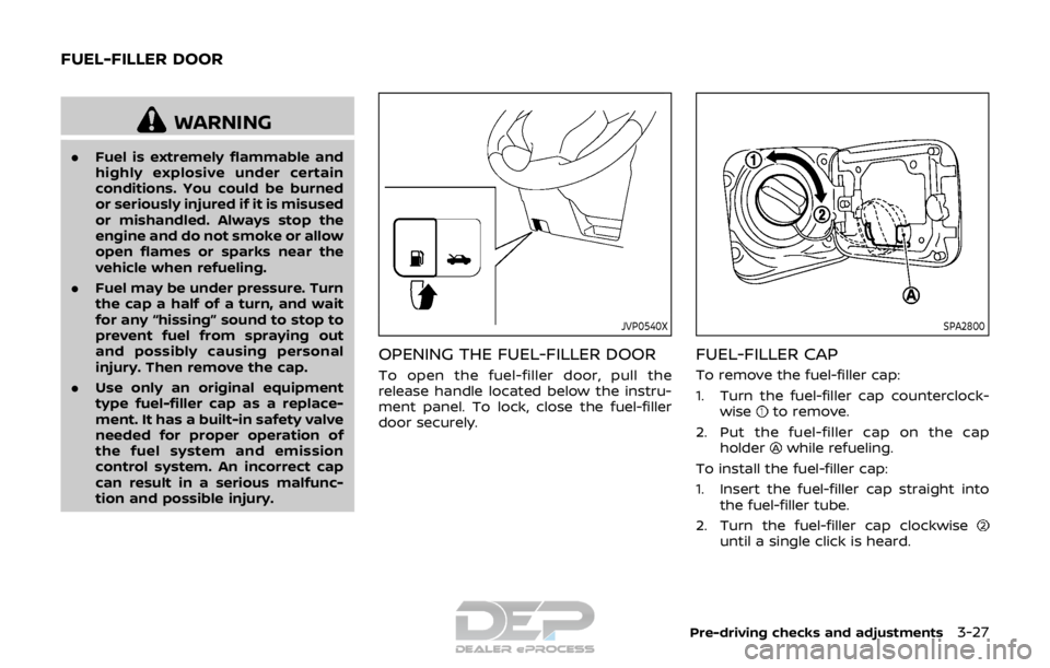
OPENING THE FUEL-FILLER DOOR
To open the fuel-filler door, pull the
release handle located below the instru-
ment panel. To lock, close the fuel-filler
door securely.
SPA2800
FUEL-FILLER CAP
To remove the fuel-filler cap:
1. Turn the fuel-filler cap counterclock-
wise
to remove.
2. Put the fuel-filler cap on the cap holder
while refueling.
To install the fuel-filler cap:
1. Insert the fuel-filler cap straight into the fuel-filler tube.
2. Turn the fuel-filler cap clockwise
until a single click is heard.
Pre-driving checks and adjustments3-27
FUEL-FILLER DOOR
Page 173 of 512
3-28Pre-driving checks and adjustments
WARNING
.Gasoline is extremely flammable
and highly explosive under cer-
tain conditions. You could be
burned or seriously injured if it is
misused or mishandled. Always
stop engine and do not smoke or
allow open flames or sparks near
the vehicle when refueling.
. Do not attempt to top off the fuel
tank after the fuel pump nozzle
shuts off automatically. Contin-
ued refueling may cause fuel
overflow, resulting in fuel spray
and possibly a fire.
. Use only an original equipment
type fuel-filler cap as a replace-
ment. It has a built-in safety valve
needed for proper operation of
the fuel system and emission
control system. An incorrect cap
can result in a serious malfunc-
tion and possible injury. It could
also cause the malfunction indi-
cator light to come on.
. Never pour fuel into the throttle
body to attempt to start your
vehicle. .
Do not fill a portable fuel contain-
er in the vehicle or trailer. Static
electricity can cause an explosion
of flammable liquid, vapor or gas
in any vehicle or trailer. To reduce
the risk of serious injury or death
when filling portable fuel contain-
ers:
— Always place the container on
the ground when filling.
— Do not use electronic devices when filling.
— Keep the pump nozzle in con- tact with the container while
you are filling it.
— Use only approved portable fuel containers for flammable
liquid.
CAUTION
. If fuel is spilled on the vehicle
body, flush it away with water to
avoid paint damage.
. Insert the cap straight into the
fuel-filler tube, then tighten until
the fuel-filler cap clicks. Failure to
tighten the fuel-filler cap properly
may cause the
malfunction indicator light (MIL) to illuminate.
If the
light illuminates be-
cause the fuel-filler cap is loose
or missing, tighten or install the
cap and continue to drive the
vehicle. The
light should turn
off after a few driving trips. If the
light does not turn off after a
few driving trips, have the vehicle
inspected. It is recommended you
visit a NISSAN dealer for this
service.
For additional information, see
“Malfunction Indicator Light
(MIL)” (P.2-16).
. The LOOSE FUEL CAP warning
message will be displayed if the
fuel-filler cap is not properly tigh-
tened. It may take a few driving
trips for the message to be dis-
played. Failure to tighten the fuel-
filler cap properly after the LOOSE
FUEL CAP warning message is
displayed may cause the
Malfunction Indicator Light (MIL)
to illuminate.
Page 174 of 512
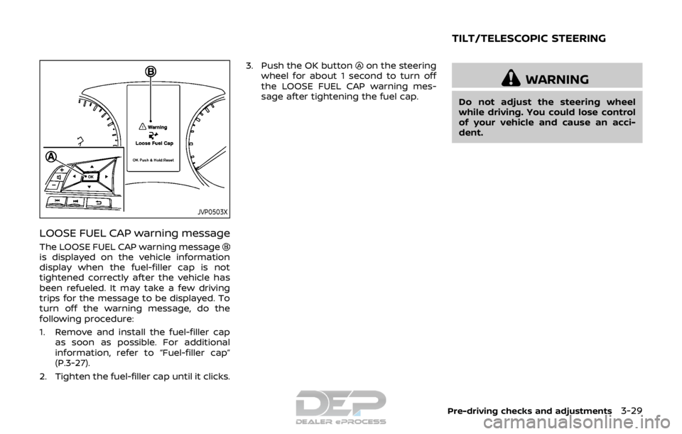
JVP0503X
LOOSE FUEL CAP warning message
The LOOSE FUEL CAP warning messageis displayed on the vehicle information
display when the fuel-filler cap is not
tightened correctly after the vehicle has
been refueled. It may take a few driving
trips for the message to be displayed. To
turn off the warning message, do the
following procedure:
1. Remove and install the fuel-filler capas soon as possible. For additional
information, refer to “Fuel-filler cap”
(P.3-27).
2. Tighten the fuel-filler cap until it clicks. 3. Push the OK button
on the steering
wheel for about 1 second to turn off
the LOOSE FUEL CAP warning mes-
sage after tightening the fuel cap.
WARNING
Do not adjust the steering wheel
while driving. You could lose control
of your vehicle and cause an acci-
dent.
Pre-driving checks and adjustments3-29
TILT/TELESCOPIC STEERING
Page 191 of 512
4-12Heater, air conditioner, audio and phone systems
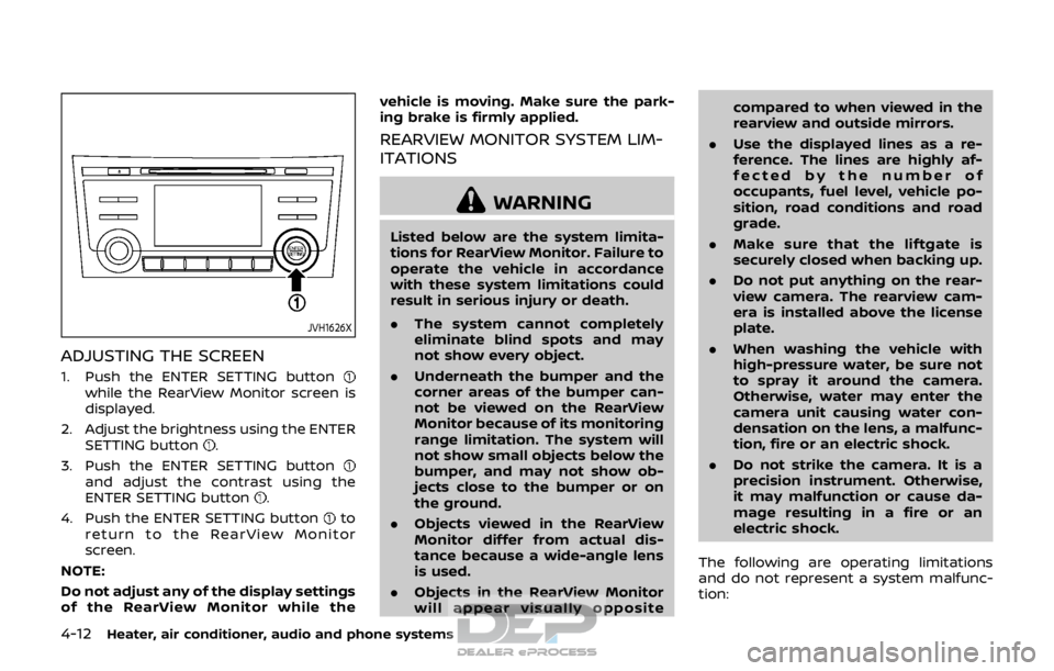
JVH1626X
ADJUSTING THE SCREEN
1. Push the ENTER SETTING buttonwhile the RearView Monitor screen is
displayed.
2. Adjust the brightness using the ENTER SETTING button
.
3. Push the ENTER SETTING button
and adjust the contrast using the
ENTER SETTING button.
4. Push the ENTER SETTING button
to
return to the RearView Monitor
screen.
NOTE:
Do not adjust any of the display settings
of the RearView Monitor while the vehicle is moving. Make sure the park-
ing brake is firmly applied.
REARVIEW MONITOR SYSTEM LIM-
ITATIONS
WARNING
Listed below are the system limita-
tions for RearView Monitor. Failure to
operate the vehicle in accordance
with these system limitations could
result in serious injury or death.
.
The system cannot completely
eliminate blind spots and may
not show every object.
. Underneath the bumper and the
corner areas of the bumper can-
not be viewed on the RearView
Monitor because of its monitoring
range limitation. The system will
not show small objects below the
bumper, and may not show ob-
jects close to the bumper or on
the ground.
. Objects viewed in the RearView
Monitor differ from actual dis-
tance because a wide-angle lens
is used.
. Objects in the RearView Monitor
will appear visually opposite compared to when viewed in the
rearview and outside mirrors.
. Use the displayed lines as a re-
ference. The lines are highly af-
fected by the number of
occupants, fuel level, vehicle po-
sition, road conditions and road
grade.
. Make sure that the liftgate is
securely closed when backing up.
. Do not put anything on the rear-
view camera. The rearview cam-
era is installed above the license
plate.
. When washing the vehicle with
high-pressure water, be sure not
to spray it around the camera.
Otherwise, water may enter the
camera unit causing water con-
densation on the lens, a malfunc-
tion, fire or an electric shock.
. Do not strike the camera. It is a
precision instrument. Otherwise,
it may malfunction or cause da-
mage resulting in a fire or an
electric shock.
The following are operating limitations
and do not represent a system malfunc-
tion:
Page 194 of 512
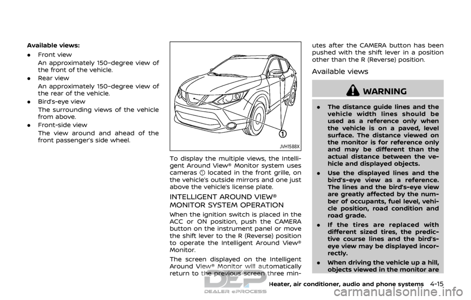
Available views:
.Front view
An approximately 150–degree view of
the front of the vehicle.
. Rear view
An approximately 150–degree view of
the rear of the vehicle.
. Bird’s-eye view
The surrounding views of the vehicle
from above.
. Front-side view
The view around and ahead of the
front passenger’s side wheel.
JVH1588X
To display the multiple views, the Intelli-
gent Around View® Monitor system uses
cameras
located in the front grille, on
the vehicle’s outside mirrors and one just
above the vehicle’s license plate.
INTELLIGENT AROUND VIEW®
MONITOR SYSTEM OPERATION
When the ignition switch is placed in the
ACC or ON position, push the CAMERA
button on the instrument panel or move
the shift lever to the R (Reverse) position
to operate the Intelligent Around View®
Monitor.
The screen displayed on the Intelligent
Around View® Monitor will automatically
return to the previous screen three min- utes after the CAMERA button has been
pushed with the shift lever in a position
other than the R (Reverse) position.
Available views
WARNING
.
The distance guide lines and the
vehicle width lines should be
used as a reference only when
the vehicle is on a paved, level
surface. The distance viewed on
the monitor is for reference only
and may be different than the
actual distance between the ve-
hicle and displayed objects.
. Use the displayed lines and the
bird’s-eye view as a reference.
The lines and the bird’s-eye view
are greatly affected by the num-
ber of occupants, fuel level, vehi-
cle position, road condition and
road grade.
. If the tires are replaced with
different sized tires, the predic-
tive course lines and the bird’s-
eye view may be displayed incor-
rectly.
. When driving the vehicle up a hill,
objects viewed in the monitor are
Heater, air conditioner, audio and phone systems4-15
Page 283 of 512

4-104Heater, air conditioner, audio and phone systems
.Previous Destinations
. Enter Address in Steps
. Cancel Route
For more information about these com-
mands, see the separate Navigation Sys-
tem Owner’s Manual.
AUDIO SYSTEM VOICE COMMANDS
To access the audio system voice com-
mands:
1. Push the
button.
2. Say “Audio”.
3. Speak a command from the following available commands:
. Play (AM, FM, etc.)
Allows user to select radio band
. Tune AM (number)
Allows user to tune directly to a
desired AM frequency
. Tune FM (number)
Allows user to tune directly to a
desired FM frequency
. SXM Channel (number)
Allows user to tune directly to a
desired SXM channel (if so equipped)
. CD Track (number)
Allows user to select track to be
played
. Play Song (name)
Allows user to select song name to be played
. Play Artist (name)
Allows user to select artist to be
played
. Play Album (name)
Allows user to select album name to
be played
For more information about the audio
system, see “FM-AM-SAT radio with Com-
pact Disc (CD) player (Type B)” (P.4-63).INFORMATION VOICE COMMANDS
The following voice commands are avail-
able for the information functions of the
Navigation System:
. Traffic
. Fuel Prices
. Sports
. Stocks
. Movie Listings
. Current Weather
. Weather Map
. 5-day Forecast
. 6-hour Forecast
. Connect To Voice Menu (if so
equipped)
For more information about these com-
mands, see the separate Navigation Sys-
tem Owner’s Manual.
MY APPS VOICE COMMANDS
Many Apps can be accessed using this
voice command. For information about
smartphone integration, “NissanCon-
nect
SMMobile Apps smartphone integra-
tion” (P.4-78).
HELP VOICE COMMANDS
The following voice commands can be
spoken to have the system provide in-
structions and tips for using the NISSAN
Voice Recognition system.
. List Commands
. What Can I Say?
. General Help
. Quit
. Exit
. Help
TROUBLESHOOTING GUIDE
The system should respond correctly to
all voice commands without difficulty. If
problems are encountered, follow the
solutions given in this guide for the
appropriate error. Where the solutions
are listed by number, try each solution in
turn, starting with number one, until the
problem is resolved.