Page 381 of 474
CHECKING ENGINE OIL LEVEL
1. Park the vehicle on a level surface andapply the parking brake.
2. Start the engine and let it idle until it reaches operating temperature.
3. Turn off the engine. Wait more than
10 minutes for the oil to drain back
into the oil pan.
4. Remove the dipstick and wipe it clean. Reinsert it all the way. 5. Remove the dipstick again and check
the oil level. It should be between the H
(High) and L (Low) marks�B. This is the
normal operating oil level range. If the
oil level is below the L (Low) mark
�A,
remove the oil filler cap and pour rec-
ommended oil through the opening.
Do not fill oil level above H (High)
mark
�C.
6. Recheck the oil level with the dipstick.
It is normal to add some oil between oil
maintenance intervals or during the
break-in period, depending on the sever-
ity of operating conditions.
Page 382 of 474
CHANGING ENGINE OIL
1. Park the vehicle on a level surface andapply the parking brake.
2. Start the engine and let it idle until it reaches operating temperature, then
turn it off. 3. Remove the oil filler cap
�Aby turning it
counterclockwise.
4. Place a large drain pan under the drain plug
�B.
5. Remove the drain plug
�Bwith a
wrench by turning it counterclockwise
and completely drain the oil.
If the oil filter is to be changed, remove
and replace it at this time. For addi-
tional information, refer to “Changing
engine oil filter” in this section.
∙
Waste oil must be disposed of properly.
∙ Check your local regulations.
Page 383 of 474
9. Turn the engine off and wait more than10 minutes. Check the oil level with the
dipstick. Add engine oil if necessary.
CHANGING ENGINE OIL FILTER
1. Park the vehicle on a level surface and
apply the parking brake.
2. Turn the engine off. 3. Place a large drain pan under the oil
filter
�B.
4. Remove pins
�Afrom the right engine
protector located inside right wheel
well, remove protector. Remove oil filter
�Bwith an oil filter wrench by turning it
counterclockwise. Then remove the oil
filter by turning it by hand.
Page 393 of 474
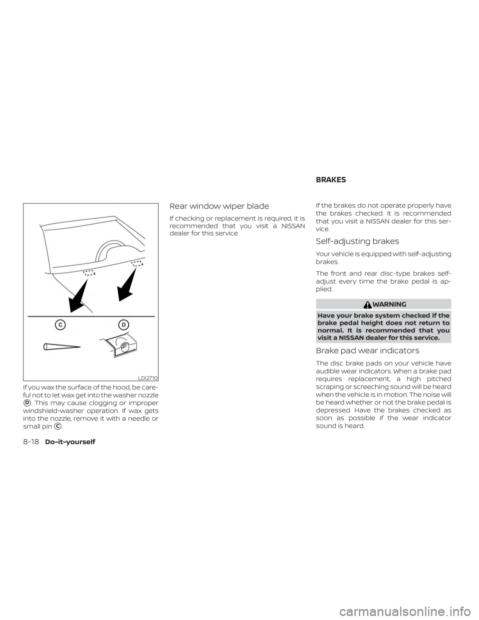
If you wax the surface of the hood, be care-
ful not to let wax get into the washer nozzle
�D. This may cause clogging or improper
windshield-washer operation. If wax gets
into the nozzle, remove it with a needle or
small pin
�C.
Rear window wiper blade
If checking or replacement is required, it is
recommended that you visit a NISSAN
dealer for this service. If the brakes do not operate properly have
the brakes checked. It is recommended
that you visit a NISSAN dealer for this ser-
vice.
Self-adjusting brakes
Your vehicle is equipped with self-adjusting
brakes.
The front and rear disc-type brakes self-
adjust every time the brake pedal is ap-
plied.
Page 394 of 474
Under some driving or climate conditions,
occasional brake squeak, squeal or other
noise may be heard. Occasional brake
noise during light to moderate stops is nor-
mal and does not affect the function or
performance of the brake system.
Proper brake inspection intervals should
be followed.For additional information re-
garding brake inspections, refer to the ap-
propriate maintenance schedule informa-
tion in the "Maintenance and schedules"
section of this manual.
ENGINE COMPARTMENT
Page 452 of 474

WARNING
Trailer hitch components have specific
weight ratings. Your vehicle may be ca-
pable of towing a trailer heavier than
the weight rating of the hitch compo-
nents. Never exceed the weight rating
of the hitch components. Doing so can
cause serious personal injury or prop-
erty damage.
Hitch ball
Choose a hitch ball of the proper size and
weight rating for your trailer:∙ The required hitch ball size is stamped on most trailer couplers. Most hitch
balls also have the size printed on the
top of the ball.
∙ Choose the proper class hitch ball based on the trailer weight.
∙ The diameter of the threaded shank of the hitch ball must be matched to the
ball mount hole diameter. The hitch ball
shank should be no more than 1/16”
smaller than the hole in the ball mount. ∙ The threaded shank of the hitch ball
must be long enough to be properly
secured to the ball mount. There should
be at least 2 threads showing beyond
the lock washer and nut.
Ball mount
The hitch ball is attached to the ball mount
and the ball mount is inserted into the
hitch receiver. Choose a proper class ball
mount based on the trailer weight. Addi-
tionally, the ball mount should be chosen to
keep the trailer tongue level with the
ground.
Weight carrying hitches
A weight carrying or “dead weight” ball
mount is one that is designed to carry the
whole amount of tongue weight and gross
weight directly on the ball mount and on
the receiver.
Weight distribution hitch
This type of hitch is also called a “load-
leveling” or “equalizing” hitch. A set of bars
attach to the ball mount and to the trailer
to distribute the tongue weight (hitch
weight) of your trailer. Many vehicles can’t
carry the full tongue weight of a given
trailer, and need some of the tongue weight transferred through the frame and
pushing down on the front wheels. This
gives stability to the tow vehicle.
A weight-distributing hitch system (Class
IV) is recommended if you plan to tow trail-
ers with a maximum weight over 5,000 lbs.
(2,268 kg). Check with the trailer and towing
equipment manufacturers to determine if
they recommend the use of a weight-
distributing hitch system.
NOTE:
A weight-distributing hitch system may
affect the operation of trailer surge
brakes. If you are considering use of a
weight-distributing hitch system with a
surge brake-equipped trailer, check with
the surge brake, hitch or trailer manufac-
turer to determine if and how this can be
done.
Follow the instructions provided by the
manufacturer for installing and using the
weight-distributing hitch system.
General set-up instructions are as follows:
1. Park unloaded vehicle on a level sur- face. With the ignition on and the doors
closed, allow the vehicle to stand for
several minutes so that it can level.
Technical and consumer information10-23
Page 455 of 474
Electric Trailer Brakes -Electric braking
systems are activated by an electronic sig-
nal sent from a trailer brake controller (spe-
cial brake-sensing module). For additional
information, refer to “Electric trailer brake
controller” in this section.
Have a professional supplier of towing
equipment make sure the trailer brakes are
properly installed and demonstrate proper
brake function testing.
Page 467 of 474
 ...................")
Coldweatherdriving.............5-80
Compass.....................2-7
Console box ..................2-59
Console light ..................2-72
Continuously Variable Transmission
(CVT) .......................5-17
Continuously Variable Transmission
(CVT) fluid ...................8-9
Driving with Continuously Variable
Transmission (CVT) ............5-17
Controls Heater and air conditioner controls . .4-33
Coolant Capacities and recommended
fuel/lubricants...............10-2
Changing engine coolant .........8-5
Checking engine coolant level ......8-5
Engine coolant temperature gauge . .2-6
Corrosionprotection..............7-7
Cruisecontrol ..............5-41,5-41
Cupholders ..................2-60
D
Daytime Running Light System ......2-42
Defroster switch Rear window and outside mirror
defrosterswitch..............2-39
Dimensions and weights ..........10-10
Dimmer switch for instrument panel . . .2-42
Door locks ....................3-5
Drivebelt ....................8-14
Drive positioner, Automatic ......3-47,3-50
Driving Coldweatherdriving...........5-80 Driving with Continuously Variable
Transmission (CVT)
............5-17
Precautions when starting and
driving.....................5-2
Drivingthevehicle...............5-17
Dual panel moonroof .............2-68
Dual power moonroof ............2-68
E
E-CALL (SOS) SWITCH .............2-53
Economy - fuel .................5-66
Emergency engine shutoff .......5-14,6-2
Emission control information label . . . .10-12
Emission control system warranty . . . .10-33
Engine Before starting the engine ........5-15
Capacities and recommended
fuel/lubricants...............10-2
Changing engine coolant .........8-5
Changing engine oil ............8-7
Changing engine oil filter .........8-8
Checking engine coolant level ......8-5
Checking engine oil level .........8-6
Engine compartment check
locations...................8-3
Engine coolant temperature gauge . .2-6
Engine cooling system ..........8-4
Engine oil ...................8-6
Engine oil and oil filter
recommendation .............10-7
Engine oil viscosity .............10-7
Engine serial number ..........10-12
Engine specifications ...........10-9 Starting the engine
............5-15
Engine Block Heater ..............5-81
Engine coolant temperature gauge ....2-6
EventDatarecorders............10-35
Exhaust gas (Carbon monoxide) .......5-2
Explanation of maintenance items .....9-2
Explanation of scheduled maintenance
items .......................9-5
Extended storage switch ..........2-56
Eyeglasscase.................2-60
F
Flashers
(Seehazardwarningflasherswitch)....6-2
Flattire......................6-3
Floormatpositioningaid...........7-6
Fluid Brakefluid..................8-10
Capacities and recommended
fuel/lubricants...............10-2
Continuously Variable Transmission (CVT)
fluid......................8-9
Engine coolant ...............8-4
Engine oil ...................8-6
Powersteeringfluid............8-9
Windshield-washer fluid .........8-11
F.M.V.S.S. certification label .........
10-12
Foglightswitch................2-43
Front air bag system
(See supplemental restraint system) . . .1-60
Front-door pocket ...............2-57
Front power seat adjustment ........1-5
Frontseats....................1-2
11-2


. For additional
information, refer to �")