Page 110 of 460
STARTUP DISPLAY
When the vehicle in placed in the ON or ACC
position the screens that display in the ve-
hicle information display include:∙ Home
∙ Audio
∙ Navigation (if so equipped)
∙ Drive computer
∙ Fuel economy
∙ Driving aids (if so equipped)
∙ Tire pressure information
∙ Warning review
∙ Settings
The warnings review title screen will show
how many active warnings exist, or 0 in the
event that no warnings are active. For ad-
ditional information on warnings and indi-
cators, refer to “Vehicle information display
warnings and indicators” in this section.
To control what items display in the vehicle
information display, refer to “Main menu se-
lection” in this section.
SETTINGS
The setting mode allows you to change the
information displayed in the vehicle infor-
mation display: ∙ Driver Assistance
∙ Customize Display
∙ Vehicle Settings
∙ Maintenance
∙ Clock
∙ TPMS Settings
∙ Unit / Language
∙ Key-Linked Settings
∙ Factory Reset
2-18Instruments and controls
Page 116 of 460

Clock
Menu itemResult
Set Clock The vehicle clock can only be adjusted from the audio center display. When selected, the user will be in-
structed to go to the settings menu in the audio center display. For additional information, refer to the sepa-
rate NissanConnect® Owner’s Manual.
TPMS Settings
The TPMS settings menu allows the user to
change the tire pressure units displayed in
the vehicle information display.
Menu item Result
Tire Pressure Unit Allows the user to select the tire pressure units that will display in the vehicle information display.
Unit/Language
The Unit/Language menu allows the user
to change the units and language shown in
the vehicle information display.
Menu item Result
Mileage/Fuel Allows user to select different mileage display units.
Tire Pressures Allows user to select different pressure display units.
Temperature Allows user to select different temperature display units.
Language Allows user to select different languages.
2-24Instruments and controls
Page 127 of 460
 — continuous high speed op-
eration
Push the lever up
�4to have one sweep
operation (MIST) of the wiper.
Pull the lever toward you
�5to operate the
washer. The wiper will also operate se")
�3High (HI) — continuous high speed op-
eration
Push the lever up
�4to have one sweep
operation (MIST) of the wiper.
Pull the lever toward you
�5to operate the
washer. The wiper will also operate several
times.
NOTE:
The Speed Dependent feature may be
disabled. For additional information, re-
fer to “Vehicle information display ” in
this section.
REAR SWITCH OPERATION
If the rear window wiper operation is inter-
rupted by snow, etc., the wiper may stop
moving to protect its motor. If this occurs,
turn the wiper switch to OFF and remove
the snow, etc. on and around the wiper
arms. Af ter about 1 minute, turn the switch
ON again to operate the wiper.
The rear window wiper and washer oper-
ate when the ignition switch is in the ON
position. Turn the switch clockwise from
the OFF position to operate the wiper.
�1Intermittent (INT) — intermittent op-
eration (not adjustable)
�2Low (ON) — continuous low speed op-
eration
Push the switch forward
�3to operate the
washer. The wiper will also operate several
times.
WARNING
In freezing temperatures the washer
solution may freeze on the window and
obscure your vision. Warm the rear win-
dow with the defroster before you wash
the rear window.
CAUTION
∙ Do not operate the washer continu- ously for more than 30 seconds.
∙ Do not operate the washer if the windshield-washer fluid reservoir is
empty.
∙ Do not fill the windshield-washer fluid reservoir with windshield-washer
fluid concentrates at full strength.
Some methyl alcohol based
windshield-washer fluid concen-
trates may permanently stain the
grille if spilled while filling the
windshield-washer fluid reservoir.
LIC3101
Instruments and controls2-35
Page 194 of 460

CAUTION
∙ Do not use a fuel containing morethan 15% ethanol in your vehicle. For
additional information, refer to “Fuel
recommendation” in the “Technical
and consumer information” section of
this manual.
∙ The Loose Fuel Cap warning message will be displayed/warning will appear
if the fuel-filler cap is not properly
tightened. It may take a few driving
trips for the message to be displayed.
Failure to tighten the fuel-filler cap
properly af ter the Loose Fuel Cap
warning message is
displayed/warning appears may
cause the
Malfunction Indicator
Light (MIL) to illuminate. ∙ Failure to tighten the fuel-filler cap
properly may cause the
Mal-
function Indicator Light (MIL) to illumi-
nate. If the
light illuminates be-
cause the fuel-filler cap is loose or
missing, tighten or install the cap and
continue to drive the vehicle.
The
light should turn off af ter a
few driving trips. If the
light does
not turn off af ter a few driving trips,
have the vehicle inspected. It is rec-
ommended that you visit a NISSAN
dealer for this service.
∙ For additional information, refer to “Malfunction Indicator Light (MIL)” in
the “Instruments and controls” sec-
tion of this manual.
∙ If fuel is spilled on the vehicle body, flush it away with water to avoid paint
damage.
NOTE:
Changing ignition switch status during
the refueling process may cause a delay
in fuel gauge response. To remove the fuel-filler cap:
1. Turn the fuel-filler cap counterclock- wise to remove.
2. Put the fuel-filler cap on the cap holder
�1while refueling.
To install the fuel-filler cap: 1. Insert the fuel-filler cap straight into the fuel-filler tube.
2. Turn the fuel-filler cap clockwise until a single click is heard.
LPD2288
3-32Pre-driving checks and adjustments
Page 337 of 460
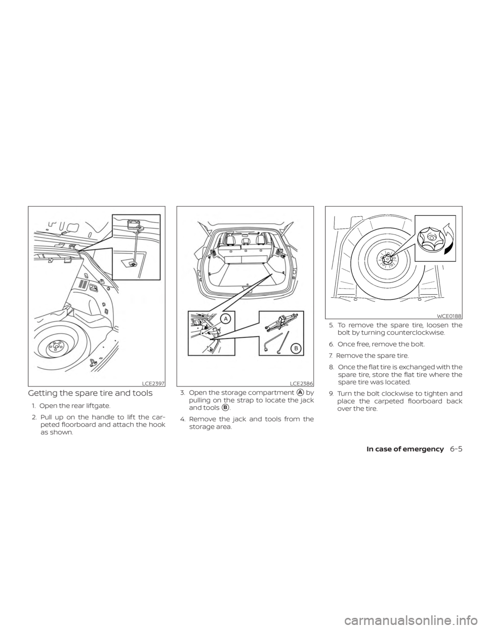
Getting the spare tire and tools
1. Open the rear lif tgate.
2. Pull up on the handle to lif t the car-peted floorboard and attach the hook
as shown. 3. Open the storage compartment
�Aby
pulling on the strap to locate the jack
and tools
�B.
4. Remove the jack and tools from the storage area. 5. To remove the spare tire, loosen the
bolt by turning counterclockwise.
6. Once free, remove the bolt.
7. Remove the spare tire.
8. Once the flat tire is exchanged with the spare tire, store the flat tire where the
spare tire was located.
9. Turn the bolt clockwise to tighten and place the carpeted floorboard back
over the tire.
LCE2397LCE2386
WCE0188
In case of emergency6-5
Page 338 of 460
Changing the spare tire with
BOSE® sub-woofer (if so
equipped)
1. To loosen the bolt, turn counterclock-wise.
2. Once free, remove the bolt. 3. Place the sub-woofer in the lower lef t
corner of the cargo area, leaning
against the driver side wall.
4. Remove the spare tire.
5. Once the flat tire is exchanged with the spare tire, store the flat tire where the
spare was located.
NOTE:
You may need to remove the wheel cap
in order to secure the damaged tire us-
ing the spare tire clamp. 6. Place the sub-woofer inside the flat tire.
7. Turn the bolt clockwise to tighten and
place the carpeted floorboard back
over the tire.
LCE2109LCE2398
6-6In case of emergency
Page 340 of 460
 off the ground. It may cause the ve-
hicle to move.
Always refer to the illustration")
∙ Do not allow passengers to stay in thevehicle while it is on the jack.
∙ Never run the engine with a wheel(s) off the ground. It may cause the ve-
hicle to move.
Always refer to the illustrations for the cor-
rect placement and jack-up points for your
specific vehicle model and jack type.
Carefully read the caution label attached
to the jack body and the following in-
structions.1. Loosen each wheel nut 1 or 2 turns by turning counterclockwise with the
wheel nut wrench. Do not remove the
wheel nuts until the tire is off the
ground. 2. Place the jack directly under the
jack-up point as illustrated so the top
of the jack contacts the vehicle at the
jack-up point. Align the jack head be-
tween the 2 notches in the front or the
rear as shown. Also fit the groove of the
jack head between the notches as
shown.
The jack should be used on firm and
level ground.
3. To lif t the vehicle, securely hold the jack lever and rod with both hands. Carefully
raise the vehicle until the tire clears the
ground. Remove the wheel nuts, and
then remove the tire.
SCE0002
6-8In case of emergency
Page 363 of 460
CHANGING ENGINE OIL
1. Park the vehicle on a level surface andapply the parking brake.
2. Start the engine and let it idle until it reaches operating temperature, then
turn it off.
3. Remove the oil filler cap
�Aby turning it
counterclockwise. 4. Remove pins
�Bfrom the under-
engine protector. 5. Place a large drain pan under the drain
plug
�C.
6. Remove the drain plug
�Cwith a
wrench by turning it counterclockwise
and completely drain the oil.
If the engine oil filter is to be changed,
remove and replace it at this time. For
additional information, refer to
“Changing engine oil filter” in this sec-
tion.
∙ Waste oil must be disposed of prop-
erly.
∙ Check your local regulations.
LDI2554LDI2558LDI2634
Do-it-yourself8-7

∙ Drive")

1. To loosen the bolt, turn counterclock-wise.
2. Once free, remove the bolt. 3. Place the sub-woofer in the lower lef t
corner of the c")
