Page 153 of 428

WARNING
∙ Do not use the HomeLink® UniversalTransceiver with any garage door
opener that lacks safety stop and re-
verse features as required by federal
safety standards. (These standards
became effective for opener models
manufactured af ter April 1, 1982.) A
garage door opener which cannot de-
tect an object in the path of a closing
garage door and then automatically
stop and reverse does not meet cur-
rent federal safety standards. Using a
garage door opener without these
features increases the risk of serious
injury or death.
∙ During the programming procedure your garage door or security gate will
open and close (if the transmitter is
within range). Make sure that people
or objects are clear of the garage door,
gate, etc., that you are programming. ∙ Your vehicle’s engine should be
turned off while programming the
HomeLink® Universal Transceiver. Do
not breathe exhaust gases; they con-
tain colorless and odorless carbon
monoxide. Carbon monoxide is dan-
gerous. It can cause unconsciousness
or death.
PROGRAMMING HOMELINK®
If you have any questions or are having
difficulty programming your HomeLink®
buttons, refer to the HomeLink® web site at:
www.homelink.com or call 1-800-355-3515.
NOTE:
Place the ignition switch in the ACC posi-
tion when programming HomeLink®. It is
also recommended that a new battery
be placed in the hand-held transmitter
of the device being programmed to
HomeLink® for quicker programming
and accurate transmission of the radio
frequency. 1. Position the end of your hand-held
transmitter 1–3 in (2–8 cm) away from
the HomeLink® surface, keeping the
HomeLink® indicator light
�1in view.
Page 167 of 428

CAUTION
The lockout protection may not func-
tion under the following conditions:
∙ When the Intelligent Key is placed ontop of the instrument panel.
∙ When the Intelligent Key is placed in- side the glove box or a storage bin.
∙ When the Intelligent Key is placed in- side the door pockets.
∙ When the Intelligent Key is placed in- side or near metallic materials.
Unlocking doors
1. Carry the Intelligent Key.
2. Push the door handle request switch.
3. The door on which the request switch was pressed will unlock and the hazard
warning lights flash once, the outside
buzzer sounds once, and the front and
tail lights may turn on for 30 seconds.
4. Push the door handle request switch again within one minute, the outside
buzzer sounds once and the remaining
doors unlock. NOTE:
∙ If “Selective Unlock” is turned off in
“Vehicle Settings,” all doors will un-
lock upon the first request switch
�1
press.
∙ Request switches for all doors and
trunk lid can be deactivated when the
“Ext. Door Switch” is switched to OFF
in “Vehicle Settings” of the vehicle in-
formation display. For additional in-
formation, refer to “Vehicle informa-
tion display ” in the “Instruments and
controls” section of this manual.
Page 179 of 428

WARNING
∙ Never allow anyone to ride in thecargo area or on the rear seat when it
is in the fold-down position. Use of
these areas by passengers without
proper restraints could result in seri-
ous injury or death in an accident or
sudden stop.
∙ Properly secure all cargo with ropes or straps to help prevent it from sliding
or shif ting. Do not place cargo higher
than the seatbacks. In a sudden stop
or collision, unsecured cargo could
cause personal injury.
∙ When returning the seatbacks to the upright position, be certain they are
completely secured in the latched po-
sition. If they are not completely se-
cured, passengers may be injured in
an accident or sudden stop.
∙ Closely supervise children when they are around cars to prevent them from
playing and becoming locked in the
trunk where they could be seriously
injured. Keep the car locked, with the
rear seatback and trunk lid securely
latched when not in use, and prevent
children’s access to car keys.
OPENING THE FUEL-FILLER DOOR
The fuel-filler door automatically unlocks
when the driver’s door is unlocked.
1. Unlock the fuel-filler door using one of the following operations.
∙ Unlock the driver’s door with the In- telligent Key.
∙ Push the power door lock switch to the unlock position.
∙ Push the door handle request switch. 2. To open the fuel-filler door, push the
right side of the fuel-filler door to re-
lease.
To lock, close the fuel-filler door securely
and lock the doors.
NOTE:
The fuel-filler door will unlock using the
key only when all doors are unlocked.
Unlocking the driver’s door will not un-
lock the fuel-filler door.
FUEL-FILLER CAP
Page 181 of 428
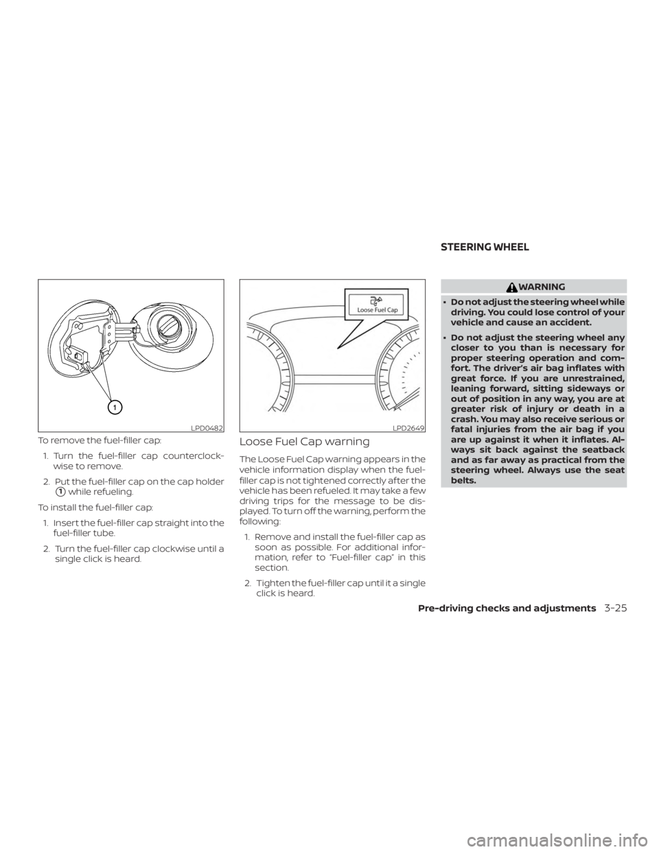
To remove the fuel-filler cap:1. Turn the fuel-filler cap counterclock- wise to remove.
2. Put the fuel-filler cap on the cap holder
�1while refueling.
To install the fuel-filler cap: 1. Insert the fuel-filler cap straight into the fuel-filler tube.
2. Turn the fuel-filler cap clockwise until a single click is heard.
Loose Fuel Cap warning
The Loose Fuel Cap warning appears in the
vehicle information display when the fuel-
filler cap is not tightened correctly af ter the
vehicle has been refueled. It may take a few
driving trips for the message to be dis-
played. To turn off the warning, perform the
following:
1. Remove and install the fuel-filler cap as soon as possible. For additional infor-
mation, refer to “Fuel-filler cap” in this
section.
2. Tighten the fuel-filler cap until it a single click is heard.
Page 194 of 428
WARNING
∙ Failure to follow the warnings and in-structions for proper use of the Rear-
View Monitor system could result in
serious injury or death.
∙ RearView Monitor is a convenience feature and is not a substitute for
proper backing. Always turn and look
out the windows and check mirrors to
be sure that it is safe to move before
operating the vehicle. Always back up
slowly.
∙ The system is designed as an aid to the driver in showing large stationary
objects directly behind the vehicle, to
help avoid damaging the vehicle.
∙ The distance guide line and the ve- hicle width line should be used as a
reference only when the vehicle is on a
level paved surface. The distance
viewed on the monitor is for reference
only and may be different than the
actual distance between the vehicle
and displayed objects.
Page 202 of 428
WARNING
∙ Failure to follow the warnings and in-structions for the proper use of the
Intelligent Around View Monitor sys-
tem could result in serious injury or
death.
∙ The Intelligent Around View Monitor is a convenience feature and is not a
substitute for proper vehicle opera-
tion because it has areas where ob-
jects cannot be viewed. The four cor-
ners of the vehicle in particular, are
areas where objects do not always
appear in the bird’s-eye, front, or rear
views. Always check your surround-
ings to be sure that it is safe to move
before operating the vehicle. Always
operate the vehicle slowly.
∙ The driver is always responsible for safety during parking and other
maneuvers.
Page 210 of 428

WARNING
Listed below are the system limitations
for Intelligent Around View Monitor.
Failure to operate the vehicle in accor-
dance with these system limitations
could result in serious injury or death.
∙ Do not use the Intelligent Around ViewMonitor with the outside mirrors in
the stored position, and make sure
that the trunk is securely closed when
operating the vehicle using the Intelli-
gent Around View Monitor.
∙ The apparent distance between ob- jects viewed on the Intelligent Around
View Monitor differs from the actual
distance.
∙ The cameras are installed on the front grille, the outside mirrors and above
the rear license plate. Do not put any-
thing on the vehicle that covers the
cameras.
∙ When washing the vehicle with high pressure water, be sure not to spray it
around the cameras. Otherwise, wa-
ter may enter the camera unit causing
water condensation on the lens, a
malfunction, fire or an electric shock. ∙ Do not strike the cameras. They are
precision instruments. Doing so could
cause a malfunction or cause damage
resulting in a fire or an electric shock.
There are some areas where the system
will not show objects and the system does
not warn of moving objects. When in the
front or rear view display, an object below
the bumper or on the ground may not be
viewed
�1. When in the bird’s-eye view, a tall
object near the seam
�2of the camera
viewing areas will not appear in the moni-
tor.
The following are operating limitations and
do not represent a system malfunction:
∙ There may be a delay when switching between views.
∙ When the temperature is extremely high or low, the screen may not display
objects clearly.
∙ When strong light directly shines on the camera, objects may not be displayed
clearly.
∙ The screen may flicker under fluores- cent light. ∙ The colors of objects on the Intelligent
Around View Monitor may differ some-
what from the actual color of objects.
∙ Objects on the Intelligent Around View Monitor may not be clear and the color
of the object may differ in a dark envi-
ronment.
∙ There may be differences in sharpness between each camera view of the
bird’s-eye view.
∙ Do not use wax on the camera lens. Wipe off any wax with a clean cloth that
has been dampened with a diluted mild
cleaning agent, then wipe with a dry
cloth.
4-20Monitor, climate, audio, phone and voice recognition systems
Page 213 of 428

WARNING
∙ Failure to follow the warnings and in-structions for proper use of the Mov-
ing Object Detection system could re-
sult in serious injury or death.
∙ The MOD system is not a substitute for proper vehicle operation and is not
designed to prevent contact with ob-
jects surrounding the vehicle. When
maneuvering, always use the outside
mirrors and rearview mirror and turn
and check the surroundings to ensure
it is safe to maneuver.
∙ The system is deactivated at speeds above 6 mph (10 km/h). It is reacti-
vated at lower speeds.
∙ The MOD system is not designed to detect surrounding stationary
objects.
The MOD system can inform the driver of
moving objects near the vehicle when
backing out of garages, maneuvering in
parking lots and in other such instances.
The MOD system detects moving objects
by using image processing technology on
the image shown in the display.
MOD SYSTEM OPERATION
The MOD system will turn on automatically
under the following conditions: ∙ When the shif t lever is in the R (Reverse) position.
∙ When vehicle speed decreases below approximately 6 mph (10 km/h) and the
camera screen is displayed.
The MOD system operates in the following
conditions when the camera view is dis-
played:∙ When the shif t lever is in the P (Park) or N (Neutral) position and the vehicle is
stopped, the MOD system detects mov-
ing objects in the bird’s-eye view. The
MOD system will not operate if the out-
side mirrors are moving in or out, in the
stowed position, or if either front door is
opened.