Page 163 of 428

CAUTION
Be sure to carry the Intelligent Key with
you when operating the vehicle.
The Intelligent Key is capable of receiving
and transmitting radio waves. The Intelli-
gent Key system transmits weak radio
waves from various distances. Environ-
mental conditions may interfere with the
operation of the Intelligent Key system un-
der the following operating conditions: ∙ When operating near a location where strong radio waves are transmitted,
such as a TV tower, power station and
broadcasting station.
∙ When in possession of wireless equip- ment, such as a cellular telephone,
transceiver, or a CB radio.
∙ When the Intelligent Key is in contact with or covered by metallic materials.
∙ When any type of radio wave remote control is used nearby.
∙ When the Intelligent Key is placed near an electric appliance such as a personal
computer.
∙ When the vehicle is parked near a park- ing meter. In such cases, correct the operating condi-
tions before using the Intelligent Key func-
tion or use the mechanical key.
Although the life of the battery varies de-
pending on the operating conditions, the
battery’s life is approximately two years. If
the battery is discharged, replace it with a
new one.
When the Intelligent Key battery is low, a
yellow indicator illuminates with the mes-
sage “Key Battery Low” in the vehicle infor-
mation display. For additional information,
refer to “Vehicle information display warn-
ings and indicators” in the “Instruments
and controls” section of this manual.
Since the Intelligent Key is capable of re-
ceiving radio waves, if the key is lef t near
equipment which transmits strong radio
waves, such as signals from a TV and per-
sonal computer, the battery life may be-
come shorter.
For additional information, refer to “Battery
replacement” in the “Do-it-yourself ” section
of this manual.
As many as four Intelligent Keys can be
registered and used with one vehicle. For
information about the purchase and use of
additional Intelligent Keys, it is recom-
mended that you visit a NISSAN dealer.
Pre-driving checks and adjustments3-7
Page 166 of 428
NOTE:∙ Request switches for all doors and
trunk lid can be deactivated when the
“Ext. Door Switch” setting is switched
to OFF in “Vehicle Settings” of the ve-
hicle information display. For addi-
tional information, refer to “Vehicle
information display ” in the “Instru-
ments and controls” section of this
manual.
∙ Doors lock with the door handle re-
quest switch
�1while the ignition
switch is not in the LOCK position. ∙
Doors do not lock by pushing the door
handle request switch while any door
is open. However, doors lock with the
mechanical key even if any door is
open.
∙ Doors do not lock with the door
handle request switch with the Intel-
ligent Key inside the vehicle and a
beep sounds to warn you. However,
when an Intelligent Key is inside the
vehicle, doors can be locked with an-
other Intelligent Key.
Page 167 of 428

CAUTION
The lockout protection may not func-
tion under the following conditions:
∙ When the Intelligent Key is placed ontop of the instrument panel.
∙ When the Intelligent Key is placed in- side the glove box or a storage bin.
∙ When the Intelligent Key is placed in- side the door pockets.
∙ When the Intelligent Key is placed in- side or near metallic materials.
Unlocking doors
1. Carry the Intelligent Key.
2. Push the door handle request switch.
3. The door on which the request switch was pressed will unlock and the hazard
warning lights flash once, the outside
buzzer sounds once, and the front and
tail lights may turn on for 30 seconds.
4. Push the door handle request switch again within one minute, the outside
buzzer sounds once and the remaining
doors unlock. NOTE:
∙ If “Selective Unlock” is turned off in
“Vehicle Settings,” all doors will un-
lock upon the first request switch
�1
press.
∙ Request switches for all doors and
trunk lid can be deactivated when the
“Ext. Door Switch” is switched to OFF
in “Vehicle Settings” of the vehicle in-
formation display. For additional in-
formation, refer to “Vehicle informa-
tion display ” in the “Instruments and
controls” section of this manual.
Page 181 of 428
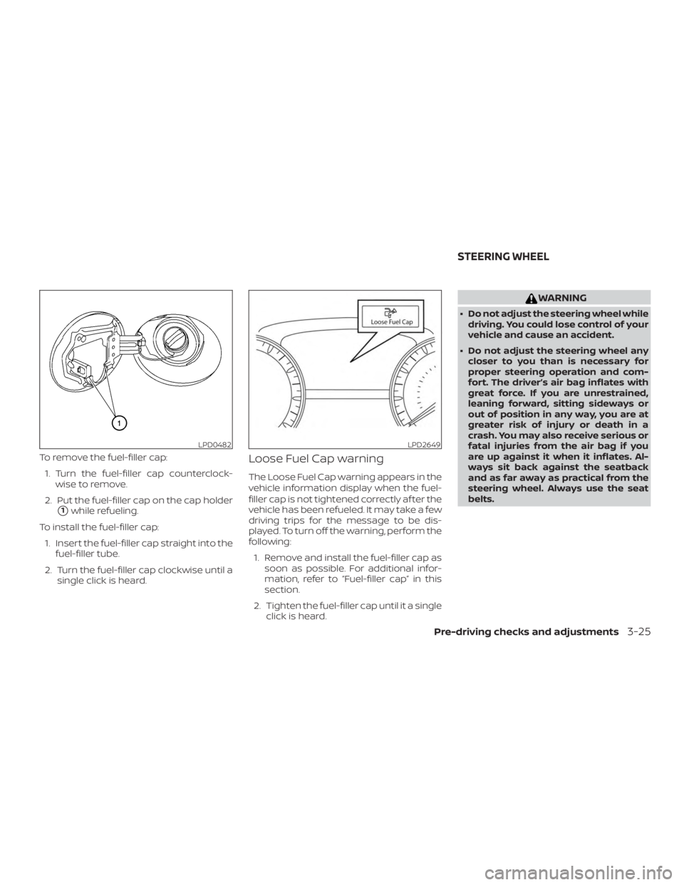
To remove the fuel-filler cap:1. Turn the fuel-filler cap counterclock- wise to remove.
2. Put the fuel-filler cap on the cap holder
�1while refueling.
To install the fuel-filler cap: 1. Insert the fuel-filler cap straight into the fuel-filler tube.
2. Turn the fuel-filler cap clockwise until a single click is heard.
Loose Fuel Cap warning
The Loose Fuel Cap warning appears in the
vehicle information display when the fuel-
filler cap is not tightened correctly af ter the
vehicle has been refueled. It may take a few
driving trips for the message to be dis-
played. To turn off the warning, perform the
following:
1. Remove and install the fuel-filler cap as soon as possible. For additional infor-
mation, refer to “Fuel-filler cap” in this
section.
2. Tighten the fuel-filler cap until it a single click is heard.
Page 194 of 428
WARNING
∙ Failure to follow the warnings and in-structions for proper use of the Rear-
View Monitor system could result in
serious injury or death.
∙ RearView Monitor is a convenience feature and is not a substitute for
proper backing. Always turn and look
out the windows and check mirrors to
be sure that it is safe to move before
operating the vehicle. Always back up
slowly.
∙ The system is designed as an aid to the driver in showing large stationary
objects directly behind the vehicle, to
help avoid damaging the vehicle.
∙ The distance guide line and the ve- hicle width line should be used as a
reference only when the vehicle is on a
level paved surface. The distance
viewed on the monitor is for reference
only and may be different than the
actual distance between the vehicle
and displayed objects.
Page 197 of 428
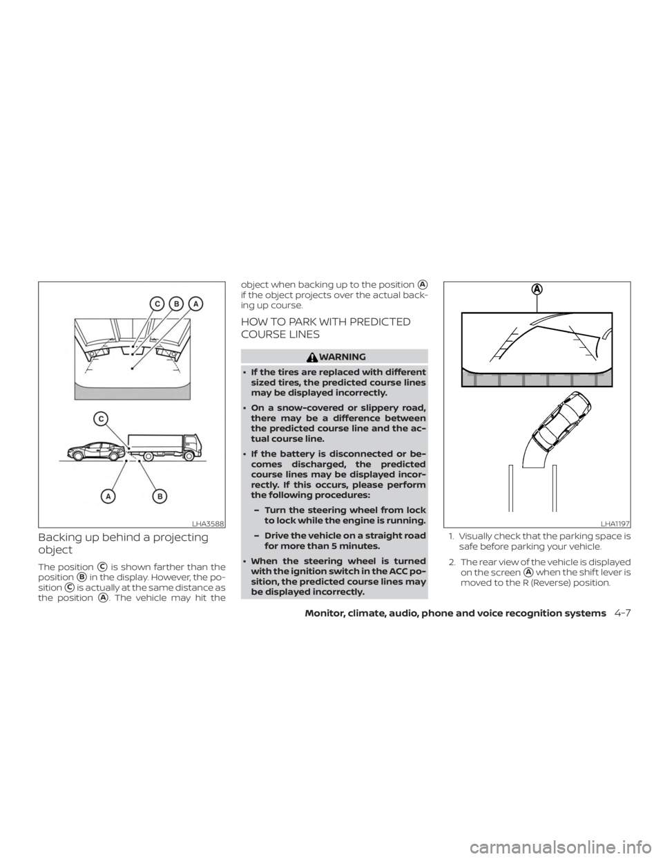
Backing up behind a projecting
object
The position�Cis shown farther than the
position
�Bin the display. However, the po-
sition
�Cis actually at the same distance as
the position
�A. The vehicle may hit the object when backing up to the position
�A
if the object projects over the actual back-
ing up course.
HOW TO PARK WITH PREDICTED
COURSE LINES
Page 199 of 428
NOTE:
Do not adjust any of the display settings
of the RearView Monitor while the ve-
hicle is moving. Make sure the parking
brake is firmly applied.
HOW TO TURN ON AND OFF
PREDICTED COURSE LINES
To toggle ON and OFF the predicted course
lines while in the P (Park) position:1. Touch the Settings key.
2. Touch the Camera key.
3. Touch the Predicted Course Lines key to turn the feature ON or OFF.
To toggle ON and OFF the predicted course
lines while in the R (Reverse) position: 1. Touch the touch-screen display.
2. Touch the Predicted Course Lines key to turn the feature ON or OFF.
REARVIEW MONITOR SYSTEM
LIMITATIONS
Page 200 of 428
∙ When strong light directly shines on thecamera, objects may not be displayed
clearly.
∙ Vertical lines may be seen in objects on the screen. This is due to strong re-
flected light from the bumper.
∙ The screen may flicker under fluores- cent light.
∙ The colors of objects on the RearView Monitor may differ somewhat from the
actual color of objects.
∙ Objects on the monitor may not be clear in a dark environment.
∙ There may be a delay when switching between views.
∙ If dirt, rain or snow accumulate on the camera, the RearView Monitor may not
display objects clearly. Clean the cam-
era.
∙ Do not use wax on the camera lens. Wipe off any wax with a clean cloth
dampened with a diluted mild cleaning
agent, then wipe with a dry cloth.
SYSTEM MAINTENANCE