Page 127 of 435

Headlight beam select
�1To select the high beam function, push
the lever forward while the low beams
are on. The high beam lights come on
and the
indicator light illumi-
nates.
�2Pull the lever back to return to the low
beam.
�3Pulling and releasing the lever flashes
the headlight high beams on and off.
The low beams do not need to be on
for this to function.
Battery saver system
The battery saver system automatically
turns off the ignition af ter a period of time
when the ignition switch is lef t in the ON
position.
The battery saver system automatically
turns off the following lights af ter a period
of time when the ignition switch is placed in
the OFF position:
∙ Headlights, when the headlight switch is in the
orposition
∙ Interior lights, when lef t in the ON posi- tion
CAUTION
Even though the battery saver feature
automatically turns off the headlights
af ter a period of time, you should turn
the headlight switch to the OFF position
when the engine is not running to avoid
discharging the vehicle battery.
DAYTIME RUNNING LIGHTS (DRL)
SYSTEM (if so equipped)
The Daytime Running Lights (DRL) portion
of the fog light assembly automatically illu-
minates when the engine is started with
the parking brake released. The DRL oper-
ate with the headlight switch in the OFF
position. Turn the headlight switch to
the
position for full illumination when
driving at night. (The DRL will turn off.)
If the parking brake is applied before the
engine is started, the DRL do not illuminate.
The DRL illuminate once the parking brake
is released. The DRL will remain on until the
ignition switch is placed in the OFF position.
It is necessary at dusk to turn the headlight
switch on for interior controls and switches
to illuminate, as those remain off while the
switch is in the OFF position.
WARNING
When the DRL system is active, tail
lights on your vehicle are not on. It is
necessary at dusk to turn on your head-
lights. Failure to do so could cause an
accident injuring yourself and others.
LIC2637
Instruments and controls2-43
Page 128 of 435
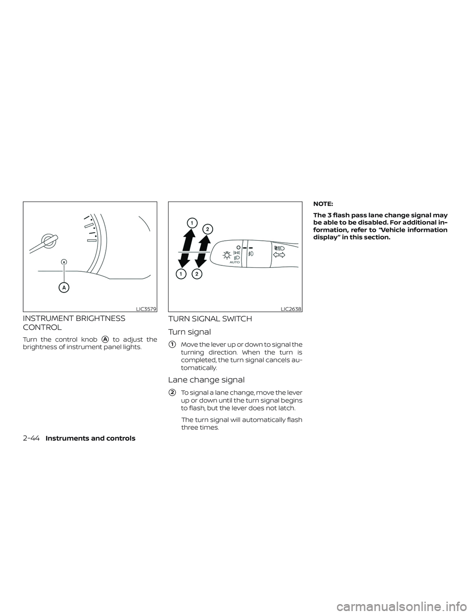
INSTRUMENT BRIGHTNESS
CONTROL
Turn the control knob�Ato adjust the
brightness of instrument panel lights.
TURN SIGNAL SWITCH
Turn signal
�1Move the lever up or down to signal the
turning direction. When the turn is
completed, the turn signal cancels au-
tomatically.
Lane change signal
�2To signal a lane change, move the lever
up or down until the turn signal begins
to flash, but the lever does not latch.
The turn signal will automatically flash
three times. NOTE:
The 3 flash pass lane change signal may
be able to be disabled. For additional in-
formation, refer to “Vehicle information
display ” in this section.
LIC3579LIC2638
2-44Instruments and controls
Page 129 of 435

To turn the fog lights on, turn the headlight
switch to the
orposition, then
turn the fog light switch to the
posi-
tion.
To turn the fog lights on with the headlight")
FOG LIGHT SWITCH (if so
equipped)
To turn the fog lights on, turn the headlight
switch to the
orposition, then
turn the fog light switch to the
posi-
tion.
To turn the fog lights on with the headlight
switch in the AUTO position, the headlights
must be on, then turn the fog light switch to
the
position.
To turn the fog lights off, turn the fog light
switch to the OFF position. To sound the horn, push near the horn icon
on the steering wheel.
WARNING
Do not disassemble the horn. Doing so
could affect proper operation of the
supplemental front air bag system.
Tampering with the supplemental front
air bag system may result in serious
personal injury.
WARNING
Do not use or allow occupants to use
the seat heater if you or the occupants
cannot monitor elevated seat tempera-
tures or have an inability to feel pain in
body parts that contact the seat. Use of
the seat heater by such people could
result in serious injury.
LIC2639LIC3568LIC3973
HORN
HEATED SEAT SWITCHES (if so
equipped)
Instruments and controls2-45
Page 130 of 435

CAUTION
∙ The battery could run down if the seatheater is operated while the engine is
not running.
∙ Do not use the seat heater for ex- tended periods or when no one is us-
ing the seat.
∙ Do not put anything on the seat which insulates heat, such as a blanket,
cushion, seat cover, etc. Otherwise,
the seat may become overheated.
∙ Do not place anything hard or heavy on the seat or pierce it with a pin or
similar object. This may result in dam-
age to the heater.
∙ Any liquid spilled on the heated seat should be removed immediately with
a dry cloth.
∙ When cleaning the seat, never use gasoline, benzine, thinner, or any
similar materials.
∙ If any malfunctions are found or the heated seat does not operate, turn
the switch off and have the system
checked. It is recommended that you
visit a NISSAN dealer for this service. The front seats are warmed by built-in
heaters.
1. Place the ignition switch in the ON po- sition.
2. Push the switch once for the high (2 in- dicators illuminated) setting. Push the
switch again for the low (1 indicator illu-
minated) setting.
The heater is controlled by a thermo-
stat, automatically turning the heater
on and off. The indicator light(s) will re-
main on as long as the switch is on.
3. Push the switch again to turn it off (no indicators illuminated).
4. When the seat is warmed or before you leave the vehicle, be sure to push the
switch to turn it off. When this switch is illuminated, the follow-
ing system is activated.
∙ Automatic Emergency Braking (AEB)
To turn the systems on, push the AEB
switch. The light will illuminate. To turn the
systems off, push the switch again. The
light will go off, and the Automatic Emer-
gency Braking (AEB) system warning light
will illuminate in the meter.
For additional information, refer to “Auto-
matic Emergency Braking (AEB)” in the
“Starting and driving” section of this
manual.
LIC3983
AUTOMATIC EMERGENCY BRAKING
(AEB) SWITCH (if so equipped)
2-46Instruments and controls
Page 131 of 435

The vehicle should be driven with the VDC
system on for most driving conditions.
If the vehicle is stuck in mud or snow, the
VDC system reduces the engine output to
reduce wheel spin. The engine speed will
be reduced even if the accelerator is de-
pressed to the floor. If maximum engine
power is needed to free a stuck vehicle,
turn the VDC system off.
To turn off the VDC system, push the VDC
OFF switch. The
indicator and the Au-
tomatic Emergency Braking (AEB) system
warning light will come on. Push the VDC OFF switch again or restart
the engine to turn on the system. For addi-
tional information, refer to “Vehicle Dy-
namic Control (VDC) system” in the “Start-
ing and driving” section of this manual.
12V OUTLETS
The power outlet is for powering electrical
accessories such as cellular telephones. It
is rated at 12 volt, 120W (10A) maximum.
The front console power outlet is powered
only when the ignition switch is in the ON
position, or while the accessory power is
active.
LIC3344
Instrument Panel
LIC4003
VEHICLE DYNAMIC CONTROL (VDC)
OFF SWITCH
POWER OUTLETS
Instruments and controls2-47
Page 132 of 435

NOTE:∙ When the ignition is in the OFF posi-
tion, the front console power outlet
stops delivering power one minute
af ter the door is opened and stays
open.
∙ If the door remains closed af ter the
ignition is placed in the OFF position,
the front console power outlet con-
tinues to deliver power until the ac-
cessory power timer has elapsed.
CAUTION
∙ The outlet and plug may be hot during or immediately af ter use.
∙ Only certain power outlets are de- signed for use with a cigarette lighter
unit. Do not use any other power out-
let for an accessory lighter. It is rec-
ommended that you visit a NISSAN
dealer for additional information.
∙ Do not use with accessories that ex- ceed a 12 volt, 120W (10A) power draw.
∙ Do not use double adapters or more than one electrical accessory. ∙ Use power outlets with the engine
running to avoid discharging the ve-
hicle battery.
∙ Avoid using power outlets when the air conditioner, headlights or rear win-
dow defroster is on.
∙ Before inserting or disconnecting a plug, be sure the electrical accessory
being used is turned off.
∙ Push the plug in as far as it will go. If good contact is not made, the plug
may overheat or the internal tem-
perature fuse may open.
∙ When not in use, be sure to close the cap. Do not allow water or any other
liquid to contact the outlet. The extended storage switch is used when
the vehicle is in transit from the factory. It is
located in the fuse panel
�Awhich is on the
driver’s side lef t kick panel, near the floor, on
the inside of the panel. If any electrical
equipment does not operate, ensure the
extended storage switch is pushed fully in
place, as shown.
LIC3581
EXTENDED STORAGE SWITCH
2-48Instruments and controls
Page 143 of 435

Driver’s side power window
switch
The driver’s side control panel is equipped
with switches to open or close all of the
windows.
To open a window, push the switch to the
detent and continue to hold down until the
desired window position is reached. To
close a window, pull the switch to the de-
tent and continue to hold up until the de-
sired window position is reached.
Front passenger’s power window
switch
The passenger’s window switch operates
only the corresponding passenger’s win-
dow. To open the window partially, push the
switch down
�1lightly until the desired
window position is reached. To close the
window partially, pull the switch up
�2until
the desired window position is reached.
Rear power window switch
The rear power window switches open or
close only the corresponding windows. To
open the window, push the switch and hold
it down
�1. To close the window, pull the
switch up
�2.
Locking passengers’ windows
When the window lock switch is depressed,
only the driver’s side window can be
opened or closed. Push it again to cancel
the window lock function.
LIC3588LIC2663
Instruments and controls2-59
Page 145 of 435

The interior light has a three-position
switch and operates regardless of ignition
switch position.
When the switch is in the ON position
�3,
the interior lights illuminate, regardless of
door position. The lights will go off af ter a
period of time unless the ignition switch is
placed in the ON position. When the switch is in the
�2position, the
interior lights will stay on for a period of
time when:
∙ The doors are unlocked by the key or the power door lock switch while all
doors are closed and the ignition switch
is placed in the OFF position.
∙ The driver’s door is opened and then closed while the key is removed from
the ignition switch.
∙ The key is removed from the ignition switch while all doors are closed.
The light will turn off while the timer is acti-
vated when: ∙ The driver’s door is locked by the key, or the power door lock switch.
∙ The ignition switch is placed in the ON position.
When the switch is in the OFF position
�1,
the interior lights do not illuminate, regard-
less of door position.
The lights will turn off automatically af ter a
period of time while doors are open to pre-
vent the battery from becoming dis-
charged.
CAUTION
Do not use for extended periods of time
with the engine stopped. This could re-
sult in a discharged battery.
LIC3985
INTERIOR LIGHTS
Instruments and controls2-61