Page 132 of 435

NOTE:∙ When the ignition is in the OFF posi-
tion, the front console power outlet
stops delivering power one minute
af ter the door is opened and stays
open.
∙ If the door remains closed af ter the
ignition is placed in the OFF position,
the front console power outlet con-
tinues to deliver power until the ac-
cessory power timer has elapsed.
CAUTION
∙ The outlet and plug may be hot during or immediately af ter use.
∙ Only certain power outlets are de- signed for use with a cigarette lighter
unit. Do not use any other power out-
let for an accessory lighter. It is rec-
ommended that you visit a NISSAN
dealer for additional information.
∙ Do not use with accessories that ex- ceed a 12 volt, 120W (10A) power draw.
∙ Do not use double adapters or more than one electrical accessory. ∙ Use power outlets with the engine
running to avoid discharging the ve-
hicle battery.
∙ Avoid using power outlets when the air conditioner, headlights or rear win-
dow defroster is on.
∙ Before inserting or disconnecting a plug, be sure the electrical accessory
being used is turned off.
∙ Push the plug in as far as it will go. If good contact is not made, the plug
may overheat or the internal tem-
perature fuse may open.
∙ When not in use, be sure to close the cap. Do not allow water or any other
liquid to contact the outlet. The extended storage switch is used when
the vehicle is in transit from the factory. It is
located in the fuse panel
�Awhich is on the
driver’s side lef t kick panel, near the floor, on
the inside of the panel. If any electrical
equipment does not operate, ensure the
extended storage switch is pushed fully in
place, as shown.
LIC3581
EXTENDED STORAGE SWITCH
2-48Instruments and controls
Page 134 of 435
WARNING
To ensure proper operation of the pas-
senger’s NISSAN Advanced Air Bag Sys-
tem, please observe the following
items:
∙ Do not allow a passenger in the rearseat to push or pull on the seatback
pocket or head restraint/headrest.
∙ Do not place heavy loads heavier than 9.1 lbs. (4 kg) on the seatback, head
restraint/headrest or in the seatback
pocket.
STORAGE TRAYS
WARNING
Do not place sharp objects in the trays
to help prevent injury in an accident or
sudden stop.
Storage compartment
LIC4004
Instrument panel pocket
LIC3558
2-50Instruments and controls
Page 143 of 435

Driver’s side power window
switch
The driver’s side control panel is equipped
with switches to open or close all of the
windows.
To open a window, push the switch to the
detent and continue to hold down until the
desired window position is reached. To
close a window, pull the switch to the de-
tent and continue to hold up until the de-
sired window position is reached.
Front passenger’s power window
switch
The passenger’s window switch operates
only the corresponding passenger’s win-
dow. To open the window partially, push the
switch down
�1lightly until the desired
window position is reached. To close the
window partially, pull the switch up
�2until
the desired window position is reached.
Rear power window switch
The rear power window switches open or
close only the corresponding windows. To
open the window, push the switch and hold
it down
�1. To close the window, pull the
switch up
�2.
Locking passengers’ windows
When the window lock switch is depressed,
only the driver’s side window can be
opened or closed. Push it again to cancel
the window lock function.
LIC3588LIC2663
Instruments and controls2-59
Page 159 of 435
 to lock the door. Put the Intel-
ligent Key in a purse, pocket or yo")
NOTE:
The doors may not lock when the Intelli-
gent Key is in the same hand that is op-
erating the request switch (if so
equipped) to lock the door. Put the Intel-
ligent Key in a purse, pocket or your
other hand.
CAUTION
The lockout protection may not func-
tion under the following conditions:
∙ When the Intelligent Key is placed ontop of the instrument panel.
∙ When the Intelligent Key is placed in- side the glove box or a storage bin.
∙ When the Intelligent Key is placed in- side the door pockets.
∙ When the Intelligent Key is placed in- side or near metallic materials.
Unlocking doors
1. Carry the Intelligent Key. 2. Push the door handle request switch (if
so equipped)�1or the lif tgate request
switch (if so equipped)
�2.
3. The hazard warning lights flash once and the outside chime sounds once.
4. Push the door handle request switch (if so equipped)
�1again within 30 sec-
onds to unlock all doors and the lif t-
gate.
LPD2798LPD2816
Pre-driving checks and adjustments3-11
Page 163 of 435
 has been pushed and the Intelligent Key is")
The panic alarm stops when:∙ It has run for a period of time, or
∙ Any button is pressed on the Intelligent Key.
∙ The request switch (if so equipped) has been pushed and the Intelligent Key is in
range of the door handle.
Battery indicator light
Battery indicator light illuminates when
you push any button. The number of blink-
ing is different to identif y each registered
Intelligent Keys. If the light does not illumi-
nate, the battery is weak or needs replace-
ment. For additional information, refer to
“Battery replacement” in the “Do-it-
yourself ” section of this manual.
WARNING SIGNALS
To help prevent the vehicle from moving
unexpectedly by erroneous operation of
the Intelligent Key or to help prevent the
vehicle from being stolen, a chime or
buzzer sounds from inside and outside the
vehicle and a warning is displayed in the
instrument panel.
When a chime or beep sounds or a warning
is displayed, be sure to check the vehicle
and the Intelligent Key.
For additional information, refer to
“Troubleshooting guide” in this section and
“Vehicle information display” in the “Instru-
ments and controls” section of this manual.
LPD2801
Pre-driving checks and adjustments3-15
Page 172 of 435
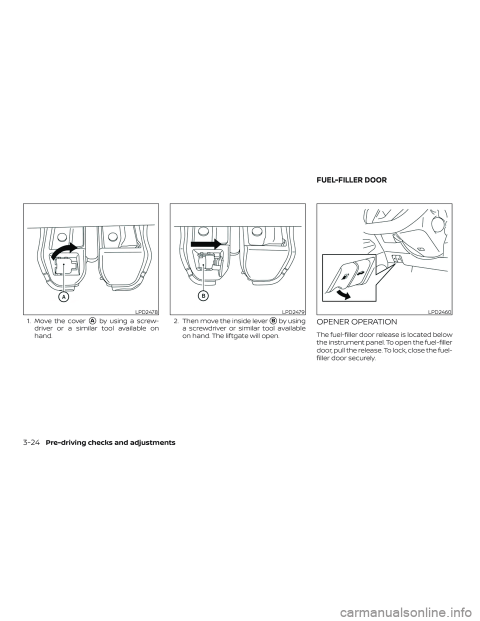
1. Move the cover�Aby using a screw-
driver or a similar tool available on
hand. 2. Then move the inside lever�Bby using
a screwdriver or similar tool available
on hand. The lif tgate will open.OPENER OPERATION
The fuel-filler door release is located below
the instrument panel. To open the fuel-filler
door, pull the release. To lock, close the fuel-
filler door securely.
LPD2478LPD2479LPD2460
FUEL-FILLER DOOR
3-24Pre-driving checks and adjustments
Page 219 of 435

MANUAL OPERATION
Fan speed control
Turn thefan speed control dial to
manually control the fan speed.
Press the AUTO button to return to auto-
matic control of the fan speed.
Temperature control dial
The temperature control dial allows you to
adjust the temperature of the outlet air. To
lower the temperature, turn the dial to the
lef t. To increase the temperature, turn the
dial to the right.
Air recirculation
Press theair recirculation button to
recirculate interior air inside the vehicle.
A/C (air conditioner) button
Start the engine, turn thefan control
dial to the desired position and press
the
button to turn on the air condi-
tioner. To turn off the air conditioner, press
the
button again.
The air conditioner cooling function op-
erates only when the engine is running.
Air flow control
Press the MODE button to manually control
air flow and select the air outlet.
— Air flows from center and side vents.
— Air flows from center and sidevents and foot outlets.
— Air flows mainly from footoutlets.
— Air flows from defroster andfoot outlets.
To turn system off
To turn off the heater and air conditioner,
press the ON-OFF button. Press the ON-
OFF button again, the system will turn on in
the mode which was used immediately
before the system was turned off.
Rear window and outside mirror
(if so equipped) defroster switch
For additional information, refer to “Rear
window and/or outside mirror defroster
switch (if so equipped)” in the “Instruments
and controls” section of this manual.
OPERATING TIPS
The sunload sensor, located on the driver’s
side of the instrument panel, as shown,
helps the system maintain a constant
temperature. Do not put anything on or
around this sensor.
∙ When the engine coolant temperature and outside air temperature are low, the
air flow from the foot outlets may not
operate for a maximum of 150 seconds.
However, this is not a malfunction. Af ter
the coolant temperature warms up, air
flow from the foot outlets will operate
normally.
LHA4125
Monitor, climate, audio, phone and voice recognition systems4-41
Page 276 of 435

If the battery of the vehicle is discharged,
the ignition switch cannot be moved
from the LOCK position.
Some indicators and warnings for opera-
tion are displayed on the vehicle informa-
tion display (if so equipped). For additional
information, refer to “Vehicle information
display” in the “Instruments and controls”
section of this manual.
OPERATING RANGE
The Intelligent Key functions can only be
used when the Intelligent Key is within the
specified operating range.
When the Intelligent Key battery is almost
discharged or strong radio waves are pres-
ent near the operating location, the Intelli-
gent Key system’s operating range be-
comes narrower and may not function
properly.
If the Intelligent Key is within the operating
range, it is possible for anyone, even some-
one who does not carry the Intelligent Key, to
push the ignition switch to start the engine.
The operating range of the engine start
function is inside of the vehicle
�1.
∙ The luggage area is not included in the operating range, but the Intelligent Key
may function.
∙ If the Intelligent Key is placed on the instrument panel, inside the glove box,
storage bin or door pocket, the Intelli-
gent Key may not function.
∙ If the Intelligent Key is placed near the door or window outside the vehicle, the
Intelligent Key may function.
PUSH-BUTTON IGNITION SWITCH
POSITIONS
LOCK (Normal parking position)
The ignition switch can only be locked in
this position.
The ignition switch will be unlocked when it
is pushed to the ON position while carrying
the Intelligent Key.
The ignition switch will lock when any door
is opened or closed with the ignition
switched off.
LSD2020
5-10Starting and driving