Page 145 of 467
If the moonroof does not operate properly
af ter performing the procedure above,
have your vehicle serviced. It is recom-
mended that you visit a NISSAN dealer for
this service.
Auto-reverse function (when
closing or tilting down the
moonroof )
The auto-reverse function can be acti-
vated when the moonroof is closed or
tilted down by automatic operation when
the ignition switch is placed in the ON po-
sition or for a period of time af ter the igni-
tion switch is placed in the OFF position.
Depending on the environment or driv-
ing conditions, the auto-reverse func-
tion may be activated if an impact or
load similar to something being caught
in the moonroof occurs.
Page 146 of 467
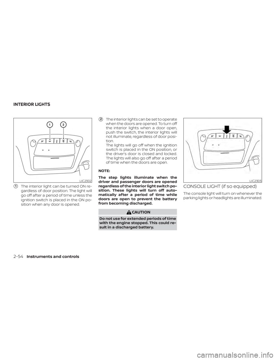
�1The interior light can be turned ON re-
gardless of door position. The light will
go off af ter a period of time unless the
ignition switch is placed in the ON po-
sition when any door is opened.
�2The interior lights can be set to operate
when the doors are opened. To turn off
the interior lights when a door open,
push the switch, the interior lights will
not illuminate, regardless of door posi-
tion.
The lights will go off when the ignition
switch is placed in the ON position, or
the driver’s door is closed and locked.
The lights will also go off af ter a period
of time when the doors are open.
NOTE:
The step lights illuminate when the
driver and passenger doors are opened
regardless of the interior light switch po-
sition. These lights will turn off auto-
matically af ter a period of time while
doors are open to prevent the battery
from becoming discharged.
Page 166 of 467
Locking doors
1. Place the ignition switch in the LOCKposition.
2. Close all doors.
3. Press the
Page 169 of 467
NOTE:
If you change the answer back horn and
light flash feature with the Intelligent
Key, the vehicle information display
screen will show the current mode af ter
the ignition switch has been cycled from
the OFF to the ON position. The vehicle
information display screen can also be
used to change the answer back horn
mode.
To deactivate:Press and hold the
Page 229 of 467

CAUTION
∙ Do not force the USB device into theUSB connection port. Inserting the
USB device tilted or up-side-down
into the port may damage the port.
Make sure that the USB device is con-
nected correctly into the USB connec-
tion port.
∙ Do not grab the USB port cover (if so equipped) when pulling the USB de-
vice out of the port. This could dam-
age the port and the cover.
∙ Do not leave the USB cable in a place where it can be pulled unintentionally.
Pulling the cable may damage the
port.
For additional information, refer to your de-
vice manufacturer’s owner information re-
garding the proper use and care of the
device.
The USB port is located in the center con-
sole. Insert the USB device into the connec-
tion port.
When a compatible storage device is
plugged into the connection port, compat-
ible audio files on the storage device can be
played through the vehicle’s audio system.
Audio file operation
MEDIA button
Place the ignition switch in the ON or ACC
position and press the MEDIA button to
switch to the USB input mode. If a CD is
playing or another audio source is plugged
in through the AUX IN jack, the MEDIA but-
ton toggles between the three sources.
Play information
Information about the audio files being
played can be displayed on the display
screen of the vehicle’s audio system. De-
pending on how the audio files are en-
coded, information such as Folder, Song
and Artist will be displayed.
The track number and number of total
tracks in the folder are displayed on the
screen as well.
Page 231 of 467

CAUTION
∙ Do not force the USB device into theUSB port. Inserting the USB device
tilted or up-side-down into the port
may damage the port. Make sure that
the USB device is connected correctly
into the USB connection port.
∙ Do not grab the USB port cover (if so equipped) when pulling the USB de-
vice out of the port. This could dam-
age the port and the cover.
∙ Do not leave the USB cable in a place where it can be pulled unintentionally.
Pulling the cable may damage the
port.
For additional information, refer to your de-
vice manufacturer’s owner information re-
garding the proper use and care of the
device.
To connect an iPod® to the vehicle so that
the iPod® can be controlled with the audio
system controls and display screen, use
the USB connection port located in the
center console. Connect the iPod®-specific
end of the cable to the iPod® and the USB
end of the cable to the USB connection
port. on the vehicle. If your iPod® supports
charging via a USB connection, its battery will be charged while connected to the ve-
hicle with the ignition switch in the ACC or
ON position.
While connected to the vehicle, the iPod®
can only be operated by the vehicle audio
controls.
To disconnect the iPod® from the vehicle,
remove the USB end of the cable from the
USB connection port. on the vehicle, then
remove the cable from the iPod®.
* iPod® is a trademark of Apple Inc., regis-
tered in the U.S. and other countries.
Compatibility
The following models are compatible:
∙ iPod® Classic - 5th Generation (firmware version 1.3.0 or later)
∙ iPod® Classic - 6th Generation (firm- ware version 2.0.1 or later)
∙ iPod® Classic - 7th Generation (firmware version 2.0.4 or later)
∙ iPod® nano - 1st generation (firmware version 1.3.1 or later)
∙ iPod® nano - 2nd generation (firmware version 1.1.3 or later) ∙ iPod® nano - 3rd generation (firmware
version 1.1.3 or later)
∙ iPod® nano - 4th generation (firmware version 1.0.4 or later)
∙ iPod® nano - 5th generation (firmware version 1.0.2 or later)
∙ iPod® nano - 6th generation (firmware version 1.1 or later)
∙ iPod® Touch - 2nd generation (firmware version 4.2.1 or later)
∙ iPod® Touch - 3rd generation (firmware version 5.1 or later) (minimum iOS 5.0
required for smartphone integration)
∙ iPod® Touch - 4th generation (firmware version 5.1 or later) (minimum iOS 5.0
required for smartphone integration)
∙ iPhone® 3G (firmware version 4.2.1 or later)
∙ iPhone® 3GS (firmware version 5.1 or later) (minimum iOS 5.0 required for
smartphone integration)
∙ iPhone® 4 (firmware version 5.1 or later) (minimum iOS 5.0 required for smart-
phone integration)
Monitor, climate, audio, phone and voice recognition systems4-45
Page 258 of 467

Additional information:∙ When replacing a wheel without the TPMS such as the spare tire, the TPMS
does not monitor the tire pressure of
the spare tire.
∙ The TPMS will activate only when the vehicle is driven at speeds above
16 mph (25 km/h). Also, this system may
not detect a sudden drop in tire pres-
sure (for example, a flat tire while driv-
ing).
∙ The low tire pressure warning light does not automatically turn off when the tire
pressure is adjusted on all four tires. Af-
ter all four tires are inflated to the rec-
ommended pressure, the vehicle must
be driven at speeds above 16 mph
(25 km/h) to activate the TPMS and turn
off the low tire pressure warning light.
Use a tire pressure gauge to check the
tire pressure.
∙ The “Tire Pressure Low - Add Air” warn- ing appears in the vehicle information
display when the low tire pressure
warning light is illuminated and low tire
pressure is detected. The “Tire Pressure
Low - Add Air” warning turns off when
the low tire pressure warning light turns
off. ∙ The “Tire Pressure Low - Add Air” warn-
ing appears each time the ignition
switch is placed in the ON position as
long as the low tire pressure warning
light remains illuminated.
∙ The “Tire Pressure Low - Add Air” warn- ing does not appear if the low tire pres-
sure warning light illuminates to indi-
cate a TPMS malfunction.
∙ Tire pressure rises and falls depending on the heat caused by the vehicle’s op-
eration and the outside temperature.
Do not reduce the tire pressure af ter
driving because the tire pressure rises
af ter driving. Low outside temperature
can lower the temperature of the air
inside the tire which can cause a lower
tire inflation pressure. This may cause
the low tire pressure warning light to
illuminate. If the warning light illumi-
nates, check the tire pressure for all four
tires.
∙ The Tire and Loading Information label is located in the driver’s door opening. ∙ You can also check the tire pressure of
all tires (except the spare) on the vehicle
information display screen. The order of
the tire pressure figures displayed on
the screen corresponds with the actual
order of the tire position.
For additional information, refer to “Low tire
pressure warning light” in the “Instruments
and controls” section, “Tire Pressure Moni-
toring System (TPMS)” in the “In case of
emergency” section and “Tire pressure” in
the “Do-it-yourself ” section of this manual.
Page 263 of 467

WARNING
Do not operate the push-button igni-
tion switch while driving the vehicle ex-
cept in an emergency. (The engine will
stop when the ignition switch is pushed
three consecutive times in quick suc-
cession or the ignition switch is pushed
and held for more than 2 seconds.) If the
engine stops while the vehicle is being
driven, this could lead to a crash and
serious injury.When the ignition switch is pushed without
depressing the brake pedal, the ignition
switch will illuminate.
Push the ignition switch center:∙ Once to change to ACC.
∙ Two times to change to ON.
∙ Three times to return to OFF.
The ignition switch will automatically re-
turn to the LOCK position when any door is
either opened or closed with the switch in
the OFF position. The ignition lock is designed so that the
ignition switch cannot be placed in the OFF
position until the shif t lever is moved to the
P (Park) position.
When the ignition switch cannot be placed
in the OFF position, proceed as follows:
1. Move the shif t lever to the P (Park) posi- tion.
2. Push the ignition switch. The ignition switch position will change to the ON
position.
3. Push the ignition switch again to the OFF position.
The shif t lever can be moved from the P
(Park) position if the ignition switch is in
the ON position and the brake pedal is
depressed.
If the battery of the vehicle is discharged,
the ignition switch cannot be moved
from the LOCK position.
Some indicators and warnings for opera-
tion are displayed on the vehicle informa-
tion display. For additional information, re-
fer to “Vehicle information display” in the
“Instruments and controls” section of this
manual.