Page 284 of 592
PEDAL TYPE
To engage:Firmly depress the parking
brake.
To release:
1. Firmly apply the foot brake.
2. Move the shif t lever to the P (Park) po- sition.
3. Firmly depress the parking brake pedal and it will release.
4. Before driving, be sure the brake warn- ing light goes out.
SWITCH TYPE (models with
electronic parking brake system)
The electronic parking brake can be ap-
plied or released automatically or by oper-
ating the parking brake switch.
Automatic operation
The electronic parking brake will apply au-
tomatically if the ignition switch is placed in
the OFF position when the brake force is
maintained by the automatic brake hold
function. The electronic parking brake is automati-
cally released as soon as the vehicle starts
and the accelerator pedal is depressed
with the driver’s seat belt fastened.
Page 286 of 592

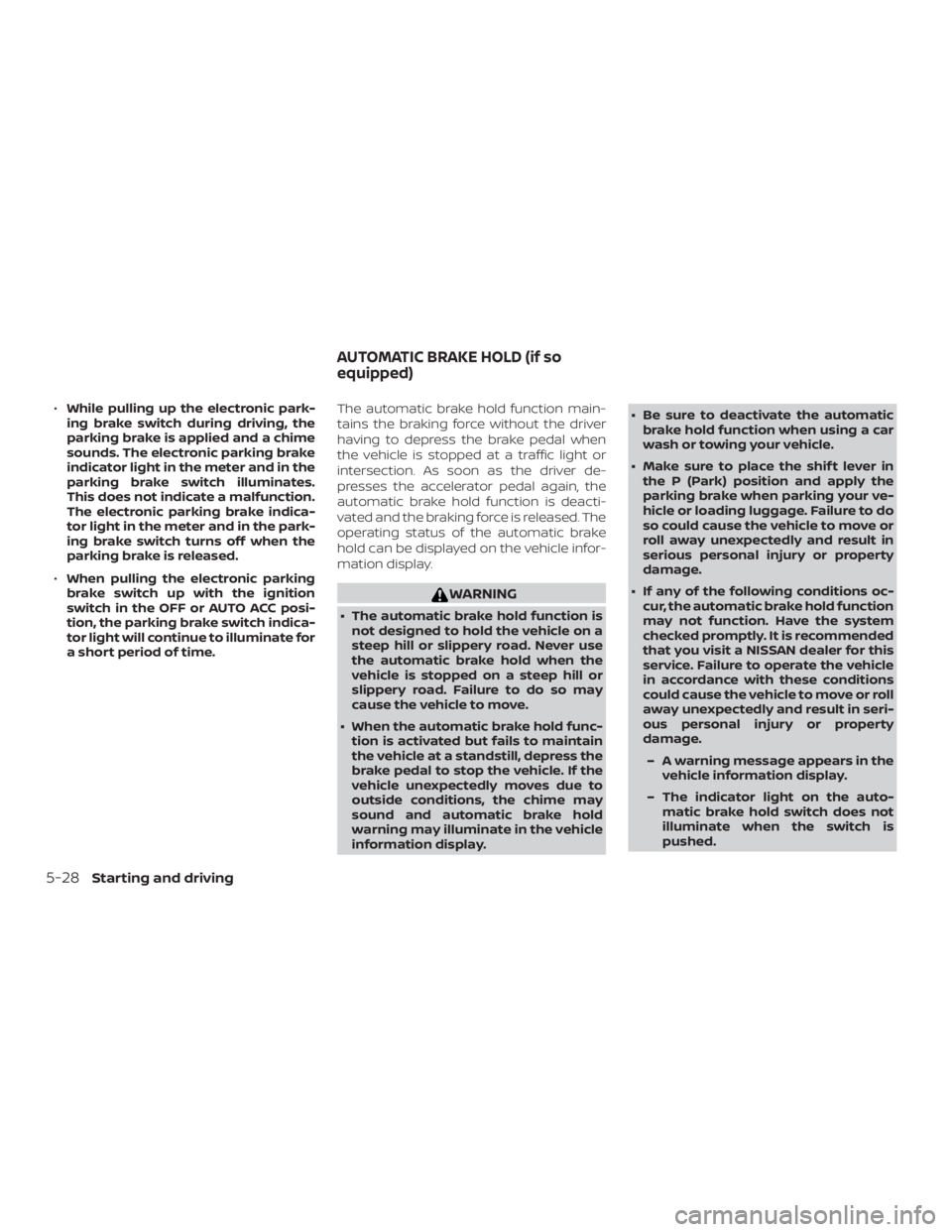
∙While pulling up the electronic park-
ing brake switch during driving, the
parking brake is applied and a chime
sounds. The electronic parking brake
indicator light in the meter and in the
parking brake switch illuminates.
This does not indicate a malfunction.
The electronic parking brake indica-
tor light in the meter and in the park-
ing brake switch turns off when the
parking brake is released.
∙ When pulling the electronic parking
brake switch up with the ignition
switch in the OFF or AUTO ACC posi-
tion, the parking brake switch indica-
tor light will continue to illuminate for
a short period of time. The automatic brake hold function main-
tains the braking force without the driver
having to depress the brake pedal when
the vehicle is stopped at a traffic light or
intersection. As soon as the driver de-
presses the accelerator pedal again, the
automatic brake hold function is deacti-
vated and the braking force is released. The
operating status of the automatic brake
hold can be displayed on the vehicle infor-
mation display.
Page 287 of 592

∙ The automatic brake hold functionwill not be activated if the Vehicle Dy-
namic Control (VDC) OFF indicator
light, electronic parking brake warn-
ing light or master warning light illu-
minate and the chassis control sys-
tem fault message appears in the
vehicle information display.
∙ To maintain the braking force to keep the vehicle to a standstill, a noise may
be heard. This is not a malfunction.
HOW TO ACTIVATE/DEACTIVATE
THE AUTOMATIC BRAKE HOLD
FUNCTION
For additional information on activating
and deactivating the automatic brake hold
function, refer to the instructions outlined
in this section.
How to activate the automatic
brake hold function
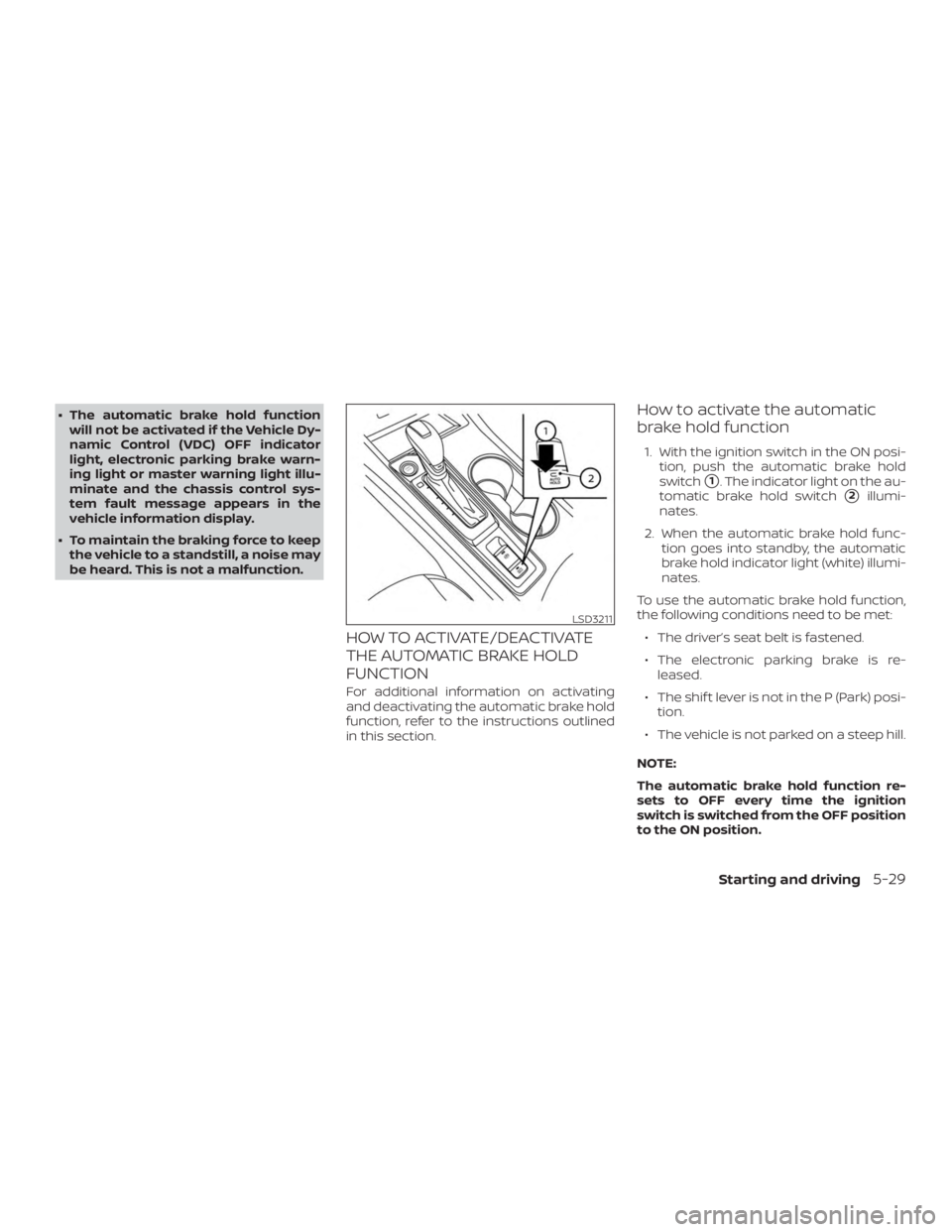
1. With the ignition switch in the ON posi- tion, push the automatic brake hold
switch
�1. The indicator light on the au-
tomatic brake hold switch
�2illumi-
nates.
2. When the automatic brake hold func- tion goes into standby, the automatic
brake hold indicator light (white) illumi-
nates.
To use the automatic brake hold function,
the following conditions need to be met: ∙ The driver’s seat belt is fastened.
∙ The electronic parking brake is re- leased.
∙ The shif t lever is not in the P (Park) posi- tion.
∙ The vehicle is not parked on a steep hill.
NOTE:
The automatic brake hold function re-
sets to OFF every time the ignition
switch is switched from the OFF position
to the ON position.
Page 427 of 592

∙ Do not leave children unattended in-side the vehicle. They could unknow-
ingly activate switches or controls or
make the vehicle move. Unattended
children could become involved in se-
rious accidents.
∙ To help avoid risk of injury or death through unintended operation of the
vehicle and/or its systems, do not
leave children, people who require the
assistance of others or pets unat-
tended in your vehicle. Additionally,
the temperature inside a closed ve-
hicle on a warm day can quickly be-
come high enough to cause a signifi-
cant risk of injury or death to people
and pets.
1. Firmly apply the parking brake.
2. Move the shif t lever to the P (Park) po- sition.
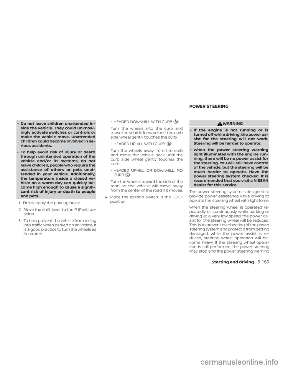
3. To help prevent the vehicle from rolling into traffic when parked on an incline, it
is a good practice to turn the wheels as
illustrated. ∙ HEADED DOWNHILL WITH CURB�A:
Turn the wheels into the curb and
move the vehicle forward until the curb
side wheel gently touches the curb.
∙ HEADED UPHILL WITH CURB
�B:
Turn the wheels away from the curb
and move the vehicle back until the
curb side wheel gently touches the
curb.
∙ HEADED UPHILL OR DOWNHILL, NO CURB
�C:
Turn the wheels toward the side of the
road so the vehicle will move away
from the center of the road if it moves.
4. Place the ignition switch in the LOCK position.
Page 429 of 592
Parking brake break-in
Break in the parking brake shoes whenever
the stopping effect of the parking brake is
weakened or whenever the parking brake
shoes and/or drums/rotors are replaced,
in order to assure the best braking perfor-
mance.
This procedure is described in the vehicle
service manual. It is recommended that
you visit a NISSAN dealer for this service.
ANTI-LOCK BRAKING SYSTEM (ABS)
Page 435 of 592

WARNING
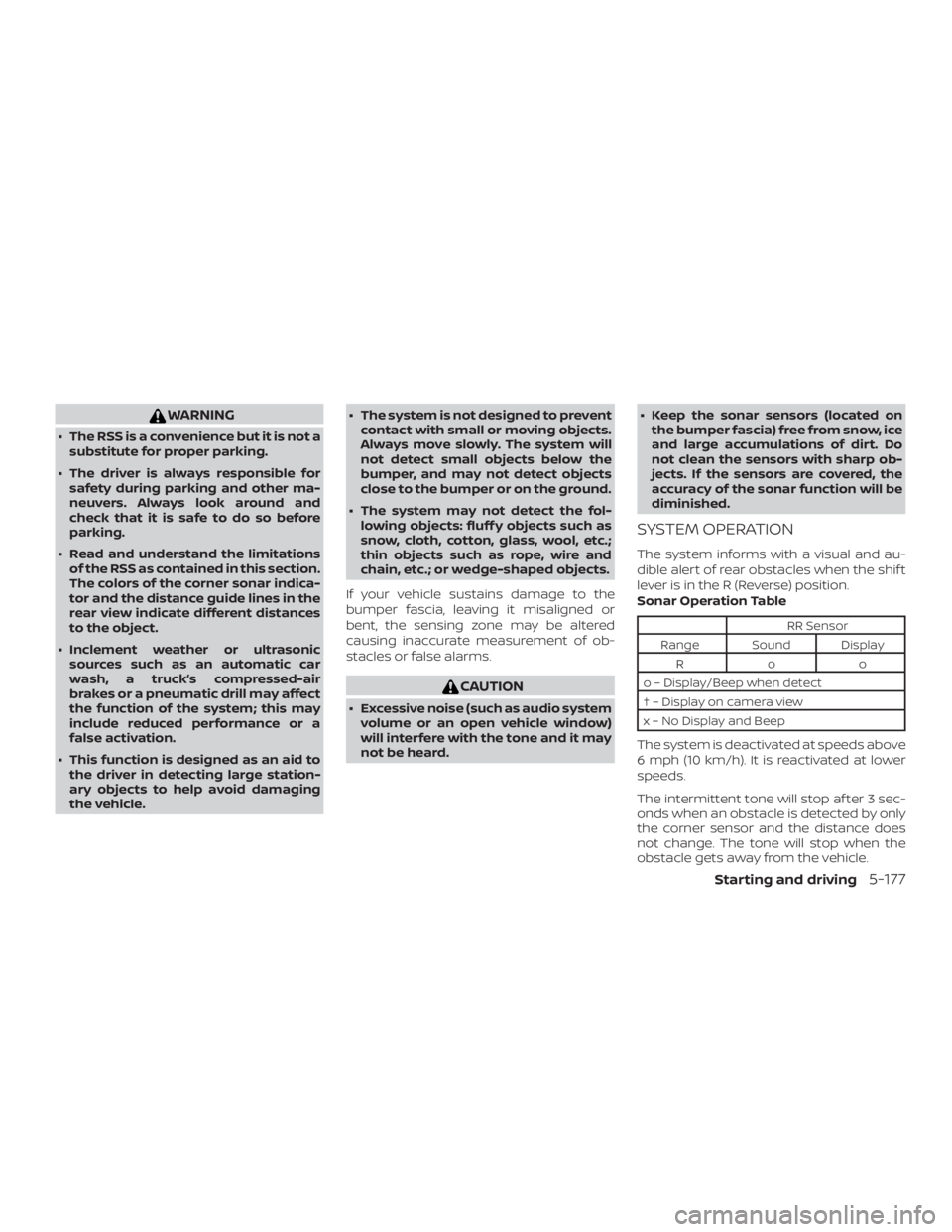
∙ The RSS is a convenience but it is not asubstitute for proper parking.
∙ The driver is always responsible for safety during parking and other ma-
neuvers. Always look around and
check that it is safe to do so before
parking.
∙ Read and understand the limitations of the RSS as contained in this section.
The colors of the corner sonar indica-
tor and the distance guide lines in the
rear view indicate different distances
to the object.
∙ Inclement weather or ultrasonic sources such as an automatic car
wash, a truck’s compressed-air
brakes or a pneumatic drill may affect
the function of the system; this may
include reduced performance or a
false activation.
∙ This function is designed as an aid to the driver in detecting large station-
ary objects to help avoid damaging
the vehicle. ∙ The system is not designed to prevent
contact with small or moving objects.
Always move slowly. The system will
not detect small objects below the
bumper, and may not detect objects
close to the bumper or on the ground.
∙ The system may not detect the fol- lowing objects: fluff y objects such as
snow, cloth, cotton, glass, wool, etc.;
thin objects such as rope, wire and
chain, etc.; or wedge-shaped objects.
If your vehicle sustains damage to the
bumper fascia, leaving it misaligned or
bent, the sensing zone may be altered
causing inaccurate measurement of ob-
stacles or false alarms.
Page 446 of 592

∙ When replacing a wheel without theTPMS such as the spare tire, the TPMS
will not function and the low tire pres-
sure warning light will flash for ap-
proximately one minute. Have your
tires replaced and/or TPMS system
reset as soon as possible. It is recom-
mended that you visit a NISSAN dealer
for these services.
∙ Replacing tires with those not origi- nally specified by NISSAN could affect
the proper operation of the TPMS.
∙ Do not inject any tire liquid or aerosol tire sealant into the tires, as this may
cause a malfunction of the tire pres-
sure sensors.
CHANGING A FLAT TIRE
If you have a flat tire, follow the instructions
below:
Stopping the vehicle
1. Safely move the vehicle off the road and
away from traffic.
2. Turn on the hazard warning flashers.
3. Park on a level surface and apply the parking brake. Move the shif t lever to P
(Park). 4. Turn off the engine.
5. Raise the hood to warn other traffic
and to signal professional road assis-
tance personnel that you need assis-
tance.
6. Have all passengers get out of the ve- hicle and stand in a safe place, away
from traffic and clear of the vehicle.
Page 452 of 592
WARNING
Always follow the instructions below.
Failure to do so could result in damage
to the charging system and cause per-
sonal injury.1. If the booster battery is in another ve- hicle, position the two vehicles to bring
their batteries near each other.
Do not allow the two vehicles to
touch. 2. Apply the parking brake. Move the shif t
lever to P (Park). Switch off all unneces-
sary electrical systems (lights, heater,
air conditioner, etc.).
3. Place the ignition switch in the LOCK position.
4. Connect the jumper cables in the se- quence illustrated (
�A,�B,�C,�D).