Page 24 of 467
1. Instrument brightness control(P. 2-35)
Trip computer reset switch (P. 2-3)
2. Vents (P. 4-11)
3. Headlight/fog light (if so
equipped)/turn signal switch
(P. 2-35)
4. Driver supplemental air bag
(P. 1-44)
Horn (P. 2-40)
5. Meters and gauges (P. 2-3) Warning and indicator lights
(P. 2-10)
Vehicle information display (P. 2-18)
6. Paddle shif ters (if so equipped)
(P. 5-14)
7. Wiper and washer switch (P. 2-34)
8. Hazard warning flasher switch
(P. 6-2)
9. Front passenger air bag status
light (P. 1-44)
10. Navigation system*
(if so equipped)
11. Front passenger supplemental air
bag (P. 1-44)
12. Glove box (P. 2-45)
13. Power outlet (P. 2-43)
14. Heater and air conditioner (P. 4-13)
LIC3763
INSTRUMENT PANEL
0-6Illustrated table of contents
Page 25 of 467
15. Shif t lever (P. 5-14)
16. USB connection port(if so equipped) (P. 4-24)
Aux jack (P. 4-24)
17. Push-button ignition switch
(P. 5-9)
18. Cruise control main/set switches
(if so equipped) (P. 5-41)
Intelligent Cruise Control (ICC)
switches (if so equipped) (P. 5-43)
Bluetooth® Hands-free Phone
System (P. 4-2, 4-54)
19. Tilt/telescopic steering wheel
controls (P. 3-28)
20. Vehicle information display
controls (P. 2-18)
Steering wheel switch for audio
control (P. 4-48)
21. Hood release (P. 3-23)
22. Trunk opener (P. 3-24) Vehicle Dynamic Control (VDC) OFF
switch (P. 2-42)
Heated steering wheel switch
(if so equipped) (P. 2-42)
*: For additional information, refer to the
separate NissanConnect® Owner’s Manual. Refer to the page number indicated in
parentheses for operating details.
Illustrated table of contents0-7
Page 90 of 467
 and all related wiring.")
SUPPLEMENTAL AIR BAG WARNING
LIGHT
The supplemental air bag warning light,
displaying
in the instrument panel,
monitors the circuits for the air bag sys-
tems, pretensioner(s) and all related wiring.
When the ignition is placed in the ON or
START position, the supplemental air bag
warning light illuminates for about 7 sec-
onds and then turns off. This means the
system is operational. If any of the following conditions occur, the
front air bag, side air bag and curtain air
bag and pretensioner systems need ser-
vicing:
∙ The supplemental air bag warning light remains on af ter approximately 7 sec-
onds.
∙ The supplemental air bag warning light flashes intermittently.
∙ The supplemental air bag warning light does not come on at all.
Under these conditions, the front air bag,
side air bag and curtain air bag or preten-
sioner systems may not operate properly.
They must be checked and repaired. It is
recommended that you visit a NISSAN
dealer for this service.WARNING
If the supplemental air bag warning
light is on, it could mean that the front
air bag, side air bag, curtain air bag
and/or pretensioner systems will not
operate in an accident. To help avoid
injury to yourself or others, have your
vehicle checked as soon as possible. It is
recommended that you visit a NISSAN
dealer for this service.
Repair and replacement
procedure
The front air bags, side air bags, curtain air
bags and pretensioner(s) are designed to
inflate on a one-time-only basis. As a re-
minder, unless it is damaged, the supple-
mental air bag warning light remains illu-
minated af ter inflation has occurred. These
systems should be repaired and/or re-
placed as soon as possible. It is recom-
mended that you visit a NISSAN dealer for
this service.
When maintenance work is required on the
vehicle, the front air bags, side air bags,
curtain air bags, pretensioner(s) and re-
lated parts should be pointed out to the
person performing the maintenance. The
ignition switch should always be placed in
the LOCK position when working under the
hood or inside the vehicle.
LRS0100
1-62Safety—Seats, seat belts and supplemental restraint system
Page 92 of 467

2 Instruments and controls
Instrument panel................................2-2
Meters and gauges ..............................2-3
Speedometer and odometer .................2-4
Tachometer ..................................2-5
Engine coolant temperature gauge ..........2-5
Fuel gauge ...................................2-6
Compass (if so equipped) ....................... 2-7
Compass display ............................. 2-7
Warning lights, indicator lights and audible
reminders ...................................... 2-10
Checking lights .............................. 2-10
Warning lights ................................ 2-11
Indicator lights .............................. 2-15
Audible reminders ........................... 2-17
Vehicle information display .....................2-18
How to use the vehicle information
display ...................................... 2-19
Startup display .............................. 2-19
Resetting the trip computer .................2-19
Settings ..................................... 2-19
Vehicle information display warnings
and indicators ............................... 2-27
Security systems ............................... 2-31
Vehicle security system .....................2-31NISSAN Vehicle Immobilizer System
.........2-32
Wiper and washer switch .......................2-34
Switch operation ............................ 2-34
Rear window and outside mirror
(if so equipped) defroster switch ................2-35
Headlight and turn signal switch ...............2-35
Headlight control switch .....................2-35
Daytime Running Lights (DRL) system
(Type A) (if so equipped) .....................2-38
LED Daytime Running Lights (DRL)
system (Type B) (if so equipped) .............2-38
Instrument brightness control ...............2-39
Turn signal switch ........................... 2-39
Fog light switch (if so equipped) .............2-40
Horn ........................................... 2-40
Heated seat switches (if so equipped) ..........2-41
Heated steering wheel switch (if so equipped) . . 2-42
Vehicle Dynamic Control (VDC) OFF switch ......2-42
E-c
all (SOS) switch (if so equipped) ..............2-43
Power outlets .................................. 2-43
Extended storage switch .......................2-44
Storage ........................................ 2-45
Front-door pockets .......................... 2-45
Seatback pockets ........................... 2-46
Page 94 of 467
1. Instrument brightness control(P. 2-35)
Trip computer reset switch (P. 2-3)
2. Vents (P. 4-11)
3. Headlight/fog light (if so
equipped)/turn signal switch
(P. 2-35)
4. Driver supplemental air bag
(P. 1-44)
Horn (P. 2-40)
5. Meters and gauges (P. 2-3) Warning and indicator lights
(P. 2-10)
Vehicle information display (P. 2-18)
6. Paddle shif ters (if so equipped)
(P. 5-14)
7. Wiper and washer switch (P. 2-34)
8. Hazard warning flasher switch
(P. 6-2)
9. Front passenger air bag status
light (P. 1-44)
10. Navigation system*
(if so equipped)
11. Front passenger supplemental air
bag (P. 1-44)
12. Glove box (P. 2-45)
13. Power outlet (P. 2-43)
14. Heater and air conditioner (P. 4-13)
LIC3763
INSTRUMENT PANEL
2-2Instruments and controls
Page 95 of 467

16. USB connection port(if so equipped) (P. 4-24)
Aux jack (P. 4-24)
17. Push-button ignition switch
(P. 5-9)
18. Cruise control main/set switches
(if so equipped) (P. 5-41)")
15. Shif t lever (P. 5-14)
16. USB connection port(if so equipped) (P. 4-24)
Aux jack (P. 4-24)
17. Push-button ignition switch
(P. 5-9)
18. Cruise control main/set switches
(if so equipped) (P. 5-41)
Intelligent Cruise Control (ICC)
switches (if so equipped) (P. 5-43)
Bluetooth® Hands-free Phone
System (P. 4-2, 4-54)
19. Tilt/telescopic steering wheel
controls (P. 3-28)
20. Vehicle information display
controls (P. 2-18)
Steering wheel switch for audio
control (P. 4-48)
21. Hood release (P. 3-23)
22. Trunk opener (P. 3-24) Vehicle Dynamic Control (VDC) OFF
switch (P. 2-42)
Heated steering wheel switch
(if so equipped) (P. 2-42)
*: For additional information, refer to the
separate NissanConnect® Owner’s Manual.
Refer to the page number indicated in
parentheses for operating details.
1. Tachometer
2. Warning and indicator lights
3. Vehicle information displayOdometer
Twin trip odometer
4. Speedometer 5. Fuel gauge
6. Engine coolant temperature gauge
LIC3459
METERS AND GAUGES
Instruments and controls2-3
Page 96 of 467
SPEEDOMETER AND ODOMETER
This vehicle is equipped with a speedom-
eter and odometer. The speedometer is
located on the right side of the meter clus-
ter. The odometer is located within the ve-
hicle information display.
Speedometer
The speedometer indicates vehicle speed.
Odometer/Twin trip odometer
The odometer and the twin trip odometer
�1are displayed in the vehicle information
display when the ignition switch is placed
in the ON position.
The odometer records the total distance
the vehicle has been driven.
The twin trip odometer records the dis-
tance of individual trips.
LIC2218LIC2921
2-4Instruments and controls
Page 97 of 467
Changing the display
Push the TRIP RESET switch
�2on the lef t
side of the instrument panel to change the
display as follows:
Trip
→ Trip→ Odometer Mile-
age →Trip
Resetting the trip odometer
Pushing the TRIP RESET switch
�2for more
than 1 second resets the currently dis-
played trip odometer to zero.
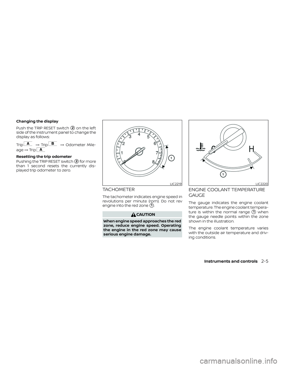
TACHOMETER
The tachometer indicates engine speed in
revolutions per minute (rpm). Do not rev
engine into the red zone
�1.
CAUTION
When engine speed approaches the red
zone, reduce engine speed. Operating
the engine in the red zone may cause
serious engine damage.
ENGINE COOLANT TEMPERATURE
GAUGE
The gauge indicates the engine coolant
temperature. The engine coolant tempera-
ture is within the normal range
�1when
the gauge needle points within the zone
shown in the illustration.
The engine coolant temperature varies
with the outside air temperature and driv-
ing conditions.
LIC2219LIC2220
Instruments and controls2-5

Trip computer reset switch (P. 2-3)
2. Vents (P. 4-11)
3. Headlight/fog light (if so
equipped)/turn signal switch
(P. 2-35)
4. Driver supplemental air bag
(P.")

16. USB connection port(if so equipped) (P. 4-24)
Aux jack (P. 4-24)
17. Push-button ignition switch
(P. 5-9)
18. Cruise control main/set switches
(if so equipped) (P. 5-41)")

Trip computer reset switch (P. 2-3)
2. Vents (P. 4-11)
3. Headlight/fog light (if so
equipped)/turn signal switch
(P. 2-35)
4. Driver supplemental air bag
(P.")