2018 NISSAN 370Z turn signal
[x] Cancel search: turn signalPage 107 of 453
SIC3981
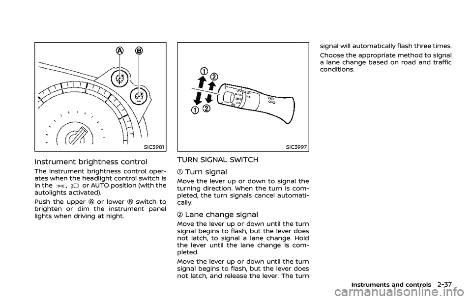
Instrument brightness control
The instrument brightness control oper-
ates when the headlight control switch is
in the
,or AUTO position (with the
autolights activated).
Push the upper
or lowerswitch to
brighten or dim the instrument panel
lights when driving at night.
SIC3997
TURN SIGNAL SWITCH
Turn signal
Move the lever up or down to signal the
turning direction. When the turn is com-
pleted, the turn signals cancel automati-
cally.
Lane change signal
Move the lever up or down until the turn
signal begins to flash, but the lever does
not latch, to signal a lane change. Hold
the lever until the lane change is com-
pleted.
Move the lever up or down until the turn
signal begins to flash, but the lever does
not latch, and release the lever. The turn signal will automatically flash three times.
Choose the appropriate method to signal
a lane change based on road and traffic
conditions.
Instruments and controls2-37
Page 124 of 453
2-54Instruments and controls
JVI0429X
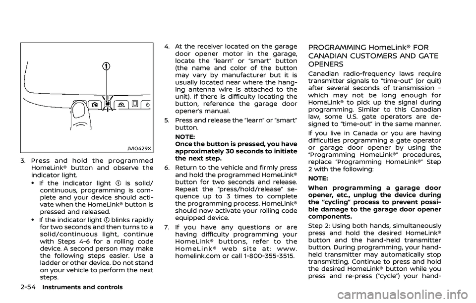
3. Press and hold the programmedHomeLink® button and observe the
indicator light.
.If the indicator lightis solid/
continuous, programming is com-
plete and your device should acti-
vate when the HomeLink® button is
pressed and released.
.If the indicator lightblinks rapidly
for two seconds and then turns to a
solid/continuous light, continue
with Steps 4-6 for a rolling code
device. A second person may make
the following steps easier. Use a
ladder or other device. Do not stand
on your vehicle to perform the next
steps. 4. At the receiver located on the garage
door opener motor in the garage,
locate the “learn” or “smart” button
(the name and color of the button
may vary by manufacturer but it is
usually located near where the hang-
ing antenna wire is attached to the
unit). If there is difficulty locating the
button, reference the garage door
opener’s manual.
5. Press and release the “learn” or “smart” button.
NOTE:
Once the button is pressed, you have
approximately 30 seconds to initiate
the next step.
6. Return to the vehicle and firmly press and hold the programmed HomeLink®
button for two seconds and release.
Repeat the “press/hold/release” se-
quence up to 3 times to complete
the programming process. HomeLink®
should now activate your rolling code
equipped device.
7. If you have any questions or are having difficulty programming your
HomeLink® buttons, refer to the
HomeLink® web site at: www.
homelink.com or call 1-800-355-3515.
PROGRAMMING HomeLink® FOR
CANADIAN CUSTOMERS AND GATE
OPENERS
Canadian radio-frequency laws require
transmitter signals to “time-out” (or quit)
after several seconds of transmission –
which may not be long enough for
HomeLink® to pick up the signal during
programming. Similar to this Canadian
law, some U.S. gate operators are de-
signed to “time-out” in the same manner.
If you live in Canada or you are having
difficulties programming a gate operator
or garage door opener by using the
“Programming HomeLink®” procedures,
replace “Programming HomeLink®” Step
2 with the following:
NOTE:
When programming a garage door
opener, etc., unplug the device during
the “cycling” process to prevent possi-
ble damage to the garage door opener
components.
Step 2: Using both hands, simultaneously
press and hold the desired HomeLink®
button and the hand-held transmitter
button. During programming, your hand-
held transmitter may automatically stop
transmitting. Continue to press and hold
the desired HomeLink® button while you
press and re-press (“cycle”) your hand-
Page 198 of 453

4-30Center display, heater, air conditioner, audio, phone and voice recognition systems
OPERATING TIPS
When the engine coolant temperature
and outside air temperature are low, the
air flow from the foot outlets may not
operate. This is not a malfunction. After
the coolant temperature warms up, air
will flow normally from the foot outlets.
The sensors
andon the instrument
panel helps maintain a constant tem-
perature. Do not put anything on or
around this sensor.
IN-CABIN MICROFILTER
The air conditioning system is equipped
with an in-cabin microfilter which collects
dirt, pollen, dust, etc. To make sure the air
conditioner heats, defogs, and ventilates
efficiently, replace the filter in accordance
with the specified maintenance intervals
listed in the “9. Maintenance and sche-
dules” section. It is recommended to see a
NISSAN dealer to replace the filter.
The filter should be replaced if air flow
is extremely decreased or when win-
dows fog up easily when operating
heater or air conditioning system.
SERVICING AIR CONDITIONER
The air conditioning system in your
NISSAN is charged with a refrigerant
designed with the environment in mind.
This refrigerant will not harm the
earth’s ozone layer. However, special
charging equipment and lubricant are
required when servicing your NISSAN air
conditioner. Using improper refrigerants
or lubricants will cause severe damage to
your air conditioning system. (See “Capa-
cities and recommended fluids/lubri-
cants” (P.10-2) for air conditioning
system refrigerant and lubricant recom-
mendations.)
Your NISSAN dealer will be able to service
your environmentally friendly air condi-
tioning system.
WARNING
The system contains refrigerant un-
der high pressure. To avoid personal
injury, any air conditioner service
should be done only by an experi-
enced technician with the proper
equipment.
AUDIO OPERATION PRECAUTIONS
Radio
Push the ignition switch to the ACC or ON
position and push the radio band select
button to turn on the radio. If you listen to
the radio with the engine not running, the
ignition switch should be pushed to the
ACC position.
Radio reception is affected by station
signal strength, distance from radio
transmitter, buildings, bridges, mountains
and other external influences. Intermit-
tent changes in reception quality nor-
mally are caused by these external
influences.
Using a cellular phone in or near the
vehicle may influence radio reception
quality.
Radio reception:
Your NISSAN radio system is equipped
with state-of-the-art electronic circuits to
enhance radio reception. These circuits
are designed to extend reception range,
and to enhance the quality of that recep-
tion.
However there are some general charac-
teristics of both FM and AM radio signals
that can affect radio reception quality in a
moving vehicle, even when the finest
equipment is used. These characteristics
AUDIO SYSTEM
Page 220 of 453
4-52Center display, heater, air conditioner, audio, phone and voice recognition systems
SAA2495
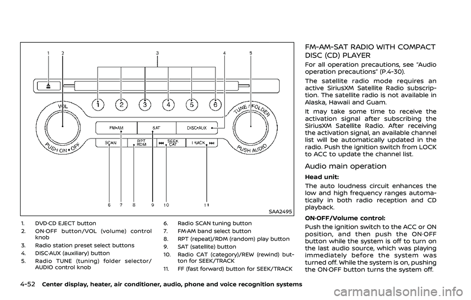
1. DVD·CD EJECT button
2. ON·OFF button/VOL (volume) controlknob
3. Radio station preset select buttons
4. DISC·AUX (auxiliary) button
5. Radio TUNE (tuning) folder selector/ AUDIO control knob 6. Radio SCAN tuning button
7. FM·AM band select button
8. RPT (repeat)/RDM (random) play button
9. SAT (satellite) button
10. Radio CAT (category)/REW (rewind) but-
ton for SEEK/TRACK
11. FF (fast forward) button for SEEK/TRACK
FM-AM-SAT RADIO WITH COMPACT
DISC (CD) PLAYER
For all operation precautions, see “Audio
operation precautions” (P.4-30).
The satellite radio mode requires an
active SiriusXM Satellite Radio subscrip-
tion. The satellite radio is not available in
Alaska, Hawaii and Guam.
It may take some time to receive the
activation signal after subscribing the
SiriusXM Satellite Radio. After receiving
the activation signal, an available channel
list will be automatically updated in the
radio. Push the ignition switch from LOCK
to ACC to update the channel list.
Audio main operation
Head unit:
The auto loudness circuit enhances the
low and high frequency ranges automa-
tically in both radio reception and CD
playback.
ON·OFF/Volume control:
Push the ignition switch to the ACC or ON
position, and then push the ON·OFF
button while the system is off to turn on
the last audio source, which was playing
immediately before the system was
turned off. While the system is on, pushing
the ON·OFF button turns the system off.
Page 221 of 453
Turn the VOL control knob to adjust the
volume.
Adjusting tone quality and speaker
balance:
To adjust Bass, Treble, Balance and Fade,
push the Audio control knob. When the
display shows the setting you want to
change (Bass, Treble, Balance and Fade),
rotate the Audio control knob to set the
desired setting. For the other setting
methods, see “How to use SETTING but-
ton” (P.4-11).
This vehicle has some sound effect func-
tions as follows:
.Speed Sensitive Vol.
For more details, see “How to use SETTING
button” (P.4-11).
Switching the display:
Pushing the DISC·AUX button will switch
the displays as follows:
iPod®/USB ?CD/DVD ?Bluetooth®
Audio ?AUX ?iPod®/USBFM-AM-SAT radio operation
radio (FM/AM) band select:
Pushing the radio band select button will
change the band as follows:
AM ?FM1 ?FM2 ?AM
radio (SAT) band select:
Pushing the radio band select button will
change the band as follows:
XM1 ?XM2 ?XM3 ?XM1
When the radio band select button is
pushed while the ignition switch is in the
ACC or ON position, the radio will come
on at the channel last played.
The last channel played will also come on
when the ON·OFF button is pushed to ON.
The satellite radio is not available in
Alaska, Hawaii and Guam.
If another audio source is playing when
the radio band select button is turned to
ON, the audio source will automatically be
turned off and the last radio channel
played will come on.
When the stereo broadcast signal is weak,
the radio will automatically change from
stereo to monaural reception. TUNE (Tuning):
. For AM and FM radio
Turn the radio TUNE knob for manual
tuning.
. For SiriusXM Satellite Radio
Turn the radio TUNE knob to seek
channels from all of the categories
when any category is not selected.
SEEK tuning/CATEGORY
(CAT):
. For AM and FM radio
Push the SEEK button
orto
tune from low to high or high to low
frequencies and to stop at the next
broadcasting station.
. For SiriusXM Satellite Radio
Push the SEEK button
orto
tune to the first channel of the next or
previous category.
During satellite radio reception, the fol-
lowing notices will be displayed under
certain conditions.
. NO SIGNAL (No signal is received while
the SAT tuner is connected.)
. OFF AIR (Broadcasting signed off)
. CHECK ANTENNA (Antenna connec-
tion error)
. LOADING (When the initial setting is
performed)
Center display, heater, air conditioner, audio, phone and voice recognition systems4-53
Page 296 of 453
5-4Starting and driving
main continuously illuminated. This se-
quence will continue upon subsequent
vehicle start-ups as long as the malfunc-
tion exists. When the malfunction indica-
tor is illuminated, the system may not be
able to detect or signal low tire pressure
as intended. TPMS malfunctions may
occur for a variety of reasons, including
the installation of replacement or alter-
nate tires or wheels on the vehicle that
prevent the TPMS from functioning prop-
erly. Always check the TPMS malfunction
telltale after replacing one or more tires
or wheels on your vehicle to ensure that
the replacement or alternate tires and
wheels allow the TPMS to continue to
function properly.
Additional information
.Since the spare tire is not equipped
with the TPMS, the TPMS does not
monitor the tire pressure of the spare
tire.
. The TPMS will activate only when the
vehicle is driven at speeds above 16
MPH (25 km/h). Also, this system may
not detect a sudden drop in tire
pressure (for example a flat tire while
driving).
. The low tire pressure warning light
does not automatically turn off when
the tire pressure is adjusted. After the
tire is inflated to the recommended pressure, the vehicle must be driven at
speeds above 16 MPH (25 km/h) to
activate the TPMS and turn off the low
tire pressure warning light. Use a tire
pressure gauge to check the tire
pressure.
. The CHECK TIRE PRESSURE warning
also appears on the vehicle informa-
tion display when the low tire pres-
sure warning light is illuminated and
low tire pressure is detected. The
CHECK TIRE PRESSURE warning turns
off when the low tire pressure warn-
ing light turns off.
The CHECK TIRE PRESSURE warning
appears each time the ignition switch
is placed in the ON position as long as
the low tire pressure warning light
remains illuminated.
The CHECK TIRE PRESSURE warning
does not appear if the low tire pres-
sure warning light illuminates to in-
dicate a TPMS malfunction.
. Tire pressure rises and falls depending
on the heat caused by the vehicle’s
operation and the outside tempera-
ture. Do not reduce the tire pressure
after driving because the tire pressure
rises after driving. Low outside tem-
perature can lower the temperature
of the air inside the tire which can
cause a lower tire inflation pressure. This may cause the low tire pressure
warning light to illuminate. If the
warning light illuminates in low ambi-
ent temperature, check the tire pres-
sure for all four tires.
For additional information, see “Low tire
pressure warning light” (P.2-13) and “Tire
Pressure Monitoring System (TPMS)” (P.6-
3).
WARNING
. If the low tire pressure warning
light illuminates while driving,
avoid sudden steering maneu-
vers or abrupt braking, reduce
vehicle speed, pull off the road
to a safe location and stop the
vehicle as soon as possible. Driv-
ing with under-inflated tires may
permanently damage the tires
and increase the likelihood of tire
failure. Serious vehicle damage
could occur and may lead to an
accident and could result in ser-
ious personal injury. Check the
tire pressure for all four tires.
Adjust the tire pressure to the
recommended COLD tire pressure
shown on the Tire and Loading
Information label to turn the low
tire pressure warning light OFF. If
Page 330 of 453
6-2In case of emergency
SIC2574
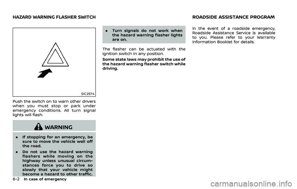
Push the switch on to warn other drivers
when you must stop or park under
emergency conditions. All turn signal
lights will flash.
WARNING
.If stopping for an emergency, be
sure to move the vehicle well off
the road.
. Do not use the hazard warning
flashers while moving on the
highway unless unusual circum-
stances force you to drive so
slowly that your vehicle might
become a hazard to other traffic. .
Turn signals do not work when
the hazard warning flasher lights
are on.
The flasher can be actuated with the
ignition switch in any position.
Some state laws may prohibit the use of
the hazard warning flasher switch while
driving. In the event of a roadside emergency,
Roadside Assistance Service is available
to you. Please refer to your Warranty
Information Booklet for details.
HAZARD WARNING FLASHER SWITCHROADSIDE ASSISTANCE PROGRAM
Page 332 of 453
6-4In case of emergency
possible. It is recommended you
visit a NISSAN dealer for these
services.
. Replacing tires with those not
originally specified by NISSAN
could affect the proper operation
of the TPMS.
. NISSAN recommends using only
Genuine NISSAN Emergency Tire
Sealant provided with your vehi-
cle. Other tire sealants may da-
mage the valve stem seal which
can cause the tire to lose air
pressure. It is recommended you
visit a NISSAN dealer as soon as
possible after using tire repair
sealant (for models equipped
with the emergency tire puncture
repair kit).CHANGING A FLAT TIRE (for models
with spare tire)
If you have a flat tire, follow the instruc-
tions below.
Stopping the vehicle
1. Safely move the vehicle off the road
and away from traffic.
2. Turn on the hazard warning flashers.
3. Park on a level surface and apply the parking brake. Move the shift lever to
the P (Park) position (Automatic trans-
mission models). Move the shift lever
to the R (Reverse) gear (Manual trans-
mission models).
4. Turn off the engine.
5. Raise the hood to warn other traffic, and to signal professional road assis-
tance personnel that you need assis-
tance.
6. Have all passengers get out of the vehicle and stand in a safe place, away
from traffic and clear of the vehicle.
WARNING
. Make sure the parking brake is
securely applied and the manual
transmission is shifted into R
(Reverse), or the automatic trans- mission into P (Park).
. Never change tires when the ve-
hicle is on a slope, ice or slippery
areas. This is hazardous.
. Never change tires if oncoming
traffic is close to your vehicle.
Wait for professional road assis-
tance.