2018 NISSAN 370Z maintenance
[x] Cancel search: maintenancePage 86 of 453

2-16Instruments and controls
Front passenger air bag sta-
tus light
The front passenger air bag status light
(), located on the center of the instru-
ment panel, will be lit and the passenger
front air bag will be OFF depending on
how the front passenger seat is being
used.
For front passenger air bag status light
operation, see “NISSAN Advanced Air Bag
System (front seats)” (P.1-36) of this man-
ual.
High beam indicator light
This light comes on when the headlight
high beam is on and goes out when the
low beam is selected.
Malfunction Indicator Light
(MIL)
If the malfunction indicator light comes
on steady or blinks while the engine is
running, it may indicate a potential emis-
sion control malfunction.
The malfunction indicator light may also
come on steady if the fuel-filler cap is
loose or missing, or if the vehicle runs out
of fuel. Check to make sure the fuel-filler
cap is installed and closed tightly, and
that the vehicle has at least 3 US gallons (11.4 liters) of fuel in the fuel tank.
After a few driving trips, the
light
should turn off if no other potential
emission control system malfunction ex-
ists.
If this indicator light remains on for 20
seconds and then blinks for 10 seconds
when the engine is not running, it indi-
cates that the vehicle is not ready for an
emission control system inspection/
maintenance test. (See “Readiness for
Inspection/Maintenance (I/M) test” (P.10-
25).)
Operation:
The malfunction indicator light will come
on in one of two ways:
. Malfunction indicator light on steady
— An emission control system mal-
function has been detected. Check
the fuel-filler cap if the LOOSE FUEL
CAP warning appears in the vehicle
information display. If the fuel-filler
cap is loose or missing, tighten or
install the cap and continue to drive
the vehicle. The
light should turn
off after a few driving trips. If the
light does not turn off after a few
driving trips, have the vehicle in-
spected. It is recommended you visit
a NISSAN dealer for this service. You
do not need to have your vehicle towed to the dealer.
. Malfunction indicator light blinking —
An engine misfire has been detected
which may damage the emission
control system.
To reduce or avoid emission control
system damage:
1) Do not drive at speeds above 45
MPH (72 km/h).
2) Avoid hard acceleration or decel- eration.
3) Avoid steep uphill grades.
4) If possible, reduce the amount of cargo being hauled or towed.
The malfunction indicator light may
stop blinking and remain on.
Have the vehicle inspected. It is re-
commended you visit a NISSAN dealer
for this service. You do not need to
have your vehicle towed to the dealer.
CAUTION
Continued vehicle operation without
having the emission control system
checked and repaired as necessary
could lead to poor driveability, re-
duced fuel economy, and possible
damage to the emission control sys-
tem.
Page 93 of 453

MAINTENANCE INDICATORS
1. Engine oil replacement indicator
This indicator appears when the set time
comes for changing the engine oil. You
can set or reset the distance for changing
the engine oil. (See “Trip computer” (P.2-
23).)
2. Oil filter replacement indicator
This indicator appears when the set time
comes for replacing the oil filter. You can
set or reset the distance for replacing the
oil filter. (See “Trip computer” (P.2-23).)
3. Tire replacement indicator
This indicator appears when the set time
comes for replacing tires. You can set or
reset the distance for replacing tires. (See
“Trip computer” (P.2-23).)
WARNING
The tire replacement indicator is not
a substitute for regular tire checks,
including tire pressure checks. See
“Changing wheels and tires” (P.8-33).
Many factors including tire inflation,
alignment, driving habits and road
conditions affect tire wear and when
tires should be replaced. Setting the
tire replacement indicator for a cer-tain driving distance does not mean
your tires will last that long. Use the
tire replacement indicator as a guide
only and always perform regular tire
checks. Failure to perform regular
tire checks, including tire pressure
checks could result in tire failure.
Serious vehicle damage could occur
and may lead to a collision, which
could result in serious personal in-
jury or death.
4. “OTHER” indicator
This indicator appears when the set time
comes for replacing items other than the
engine oil, oil filter and tires. You can set
or reset the distance for replacing the
items. (See “Trip computer” (P.2-23).)
Models with navigation system:
More maintenance reminders are also
available on the center display. (See
“How to use INFO button” (P.4-8).)SIC3978
TRIP COMPUTER
Switches for the trip computer are lo-
cated on the left side of the combination
meter panel. To operate the trip compu-
ter, push the switches as shown above.
ENTER switch
NEXT switch
When the ignition switch is pushed to the
ON position, modes of the trip computer
can be selected by pushing the
switch.
Each time the
switchis pushed, the
display will change as follows:
Current fuel consumption ?Average fuel
consumption and speed ?Elapsed time
Instruments and controls2-23
Page 98 of 453

2-28Instruments and controls
ALERT:
Alert menu can be set to notify the
following items.
.UPSHIFT
Select this submenu to set the engine
speed (RPM) of the upshift indicator.
See “Upshift indicator” (P.5-20) (MT
models) or “Manual shift mode” (P.5-
14) (AT models).
. TIMER
Select this submenu to specify when
the “TIMER” indicator activates.
. ICY
Select this submenu to display the low
outside temperature warning.
To return to the top page of the setting
mode, select “BACK”.
MAINTENANCE:
The maintenance intervals of the follow-
ing items can be set or reset for the
reminders.
. OIL
Select this submenu to set or reset the
distance for changing the engine oil.
. FILTER
Select this submenu to set or reset the
distance for replacing the oil filter.
. TIRE
Select this submenu to set or reset the
distance for replacing tires. .
OTHER
Select this submenu and set or reset
the distance for replacing items other
than the engine oil, oil filter and tires.
To return to the top page of the setting
mode, select “BACK”.
OPTIONS:
The 3 option menus can be set to your
preference.
. LANGUAGE
Select this submenu to choose English
or French for display.
. UNIT
Select this submenu to choose the
unit from US or METRIC.
. EFFECTS
Select this menu to set the dial effects
described below to on or off.
— The indicator needles sweep in the
meters when the engine is started.
To return to the top page of the setting
mode, select “BACK”.
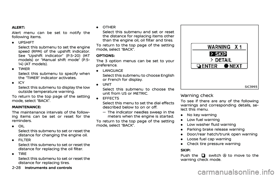
SIC3993
Warning check
To see if there are any of the following
warnings and corresponding details, se-
lect this menu.
. No key warning
. Low fuel warning
. Low washer fluid warning
. Parking brake release warning
. Door/rear hatch/trunk open warning
. Loose fuel cap warning
. Check tire pressure warning
SKIP:
Push the
switchto move to the
warning check mode.
Page 169 of 453

4 Center display, heater, air conditioner,audio, phone and voice recognition sys-
tems
Safety note ........................................................................\
................. 4-3
Center multi-function control panel (models with
navigation system) ....................................................................... 4-4
How to use multi-function controller ..................... 4-4
How to use touch screen ................................................. 4-5
Menu options ........................................................................\
..... 4-7
How to select menus on the screen ....................... 4-7
Vehicle information and settings (models with
navigation system) ....................................................................... 4-8 How to use STATUS button ........................................... 4-8
How to use brightness control and display
ON/OFF button ........................................................................\
. 4-8
How to use INFO button ................................................... 4-8
How to use SETTING button ......................................... 4-11
RearView Monitor (models with
navigation system) ..................................................................... 4-17 RearView Monitor system operation .................... 4-18
How to read displayed lines ......................................... 4-18
How to park with predictive course lines ......... 4-19
Adjusting the screen ......................................................... 4-22
Predictive course line settings .................................. 4-22
RearView Monitor system limitations .................. 4-22
System maintenance ........................................................ 4-23 Ventilators ........................................................................\
............... 4-24
Center ventilators ............................................................. 4-24
Side ventilators ................................................................... 4-24
Heater and air conditioner ................................................. 4-25
Automatic air conditioner (Type A) (if
so equipped) ........................................................................\
.. 4-26
Automatic air conditioner (Type B) (if
so equipped) ........................................................................\
.. 4-28
Operating tips ...................................................................... 4-30
In-cabin microfilter ........................................................... 4-30
Servicing air conditioner .............................................. 4-30
Audio system ........................................................................\
........ 4-30 Audio operation precautions ................................... 4-30
FM-AM radio with Compact Disc
(CD) player ........................................................................\
....... 4-43
FM-AM-SAT radio with Compact Disc
(CD) player ........................................................................\
....... 4-52
DVD (Digital Versatile Disc) player operation
(models with navigation system) ......................... 4-55
USB (Universal Serial Bus) connection port
(models with navigation system) ......................... 4-59
Bluetooth® streaming audio (models with
navigation system) ........................................................... 4-63
Page 174 of 453

4-6Center display, heater, air conditioner, audio, phone and voice recognition systems
SAA2474
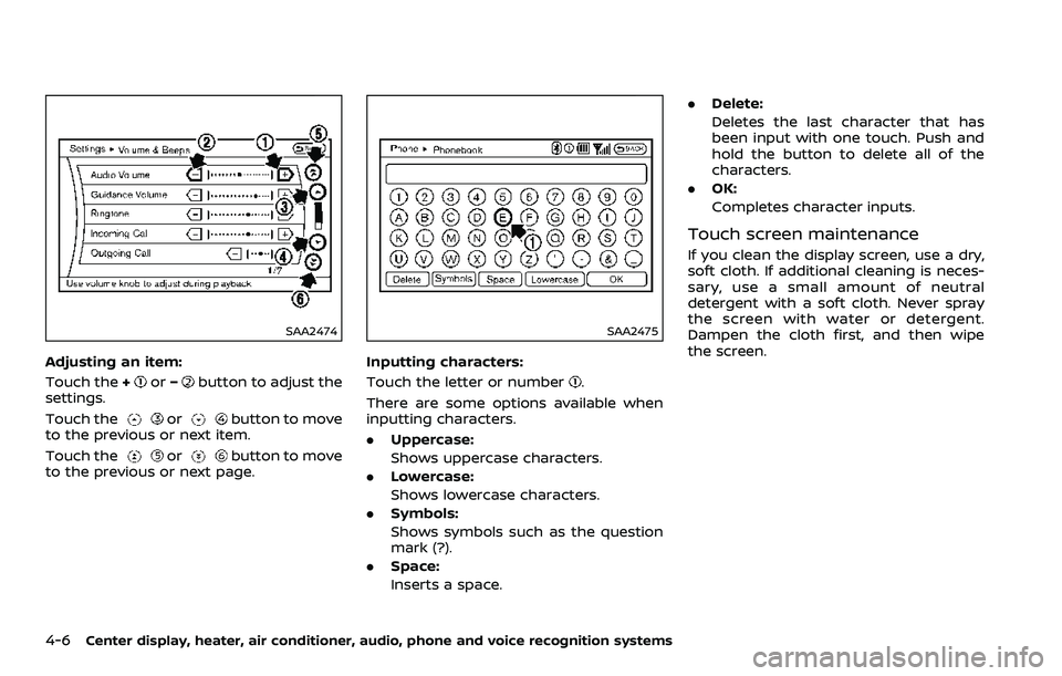
Adjusting an item:
Touch the+
or−button to adjust the
settings.
Touch the
orbutton to move
to the previous or next item.
Touch the
orbutton to move
to the previous or next page.
SAA2475
Inputting characters:
Touch the letter or number
.
There are some options available when
inputting characters.
. Uppercase:
Shows uppercase characters.
. Lowercase:
Shows lowercase characters.
. Symbols:
Shows symbols such as the question
mark (?).
. Space:
Inserts a space. .
Delete:
Deletes the last character that has
been input with one touch. Push and
hold the button to delete all of the
characters.
. OK:
Completes character inputs.
Touch screen maintenance
If you clean the display screen, use a dry,
soft cloth. If additional cleaning is neces-
sary, use a small amount of neutral
detergent with a soft cloth. Never spray
the screen with water or detergent.
Dampen the cloth first, and then wipe
the screen.
Page 178 of 453

4-10Center display, heater, air conditioner, audio, phone and voice recognition systems
SAA2481
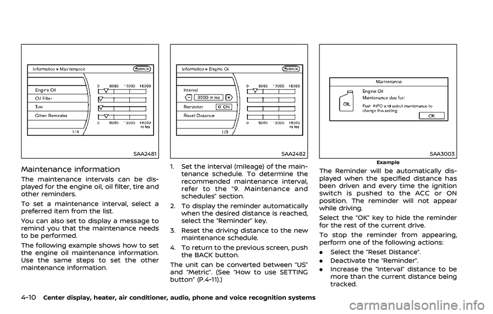
Maintenance information
The maintenance intervals can be dis-
played for the engine oil, oil filter, tire and
other reminders.
To set a maintenance interval, select a
preferred item from the list.
You can also set to display a message to
remind you that the maintenance needs
to be performed.
The following example shows how to set
the engine oil maintenance information.
Use the same steps to set the other
maintenance information.
SAA2482
1. Set the interval (mileage) of the main-tenance schedule. To determine the
recommended maintenance interval,
refer to the “9. Maintenance and
schedules” section.
2. To display the reminder automatically when the desired distance is reached,
select the “Reminder” key.
3. Reset the driving distance to the new maintenance schedule.
4. To return to the previous screen, push the BACK button.
The unit can be converted between “US”
and “Metric”. (See “How to use SETTING
button” (P.4-11).)
SAA3003
Example
The Reminder will be automatically dis-
played when the specified distance has
been driven and every time the ignition
switch is pushed to the ACC or ON
position. The reminder will not appear
while driving.
Select the “OK” key to hide the reminder
for the rest of the current drive.
To stop the reminder from appearing,
perform one of the following actions:
. Select the “Reset Distance”.
. Deactivate the “Reminder”.
. Increase the “Interval” distance to be
more than the current distance being
tracked.
Page 191 of 453

.Use the displayed lines as a re-
ference. The lines are highly af-
fected by the number of
occupants, fuel level, vehicle po-
sition, road conditions and road
grade.
. Make sure that the trunk lid or
rear hatch is securely closed
when backing up.
. Do not put anything on the rear-
view camera. The rearview cam-
era is installed above the license
plate.
. When washing the vehicle with
high-pressure water, be sure not
to spray it around the camera.
Otherwise, water may enter the
camera unit causing water con-
densation on the lens, a malfunc-
tion, fire or an electric shock.
. Do not strike the camera. It is a
precision instrument. Otherwise,
it may malfunction or cause da-
mage resulting in a fire or an
electric shock.
The following are operating limitations
and do not represent a system malfunc-
tion:
. When the temperature is extremely
high or low, the screen may not clearly display objects.
. When strong light is directly coming
on the camera, objects may not be
displayed clearly.
. Vertical lines may be seen in objects
on the screen. This is due to strong
reflected light from the bumper.
. The screen may flicker under fluores-
cent light.
. The colors of objects on the RearView
Monitor may differ somewhat from
the actual color of objects.
. Objects on the monitor may not be
clear in a dark environment.
. If dirt, rain or snow accumulates on
the camera, the RearView Monitor
may not display objects clearly. Clean
the camera.
. Do not use wax on the camera win-
dow. Wipe off any wax with a clean
cloth dampened with mild detergent
diluted with water.
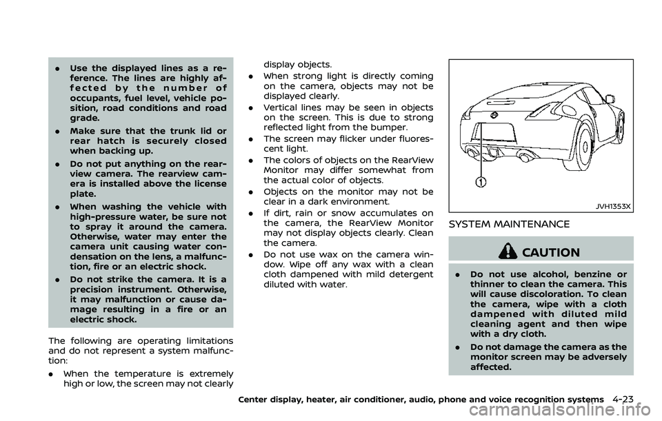
JVH1353X
SYSTEM MAINTENANCE
CAUTION
.Do not use alcohol, benzine or
thinner to clean the camera. This
will cause discoloration. To clean
the camera, wipe with a cloth
dampened with diluted mild
cleaning agent and then wipe
with a dry cloth.
. Do not damage the camera as the
monitor screen may be adversely
affected.
Center display, heater, air conditioner, audio, phone and voice recognition systems4-23
Page 198 of 453

4-30Center display, heater, air conditioner, audio, phone and voice recognition systems
OPERATING TIPS
When the engine coolant temperature
and outside air temperature are low, the
air flow from the foot outlets may not
operate. This is not a malfunction. After
the coolant temperature warms up, air
will flow normally from the foot outlets.
The sensors
andon the instrument
panel helps maintain a constant tem-
perature. Do not put anything on or
around this sensor.
IN-CABIN MICROFILTER
The air conditioning system is equipped
with an in-cabin microfilter which collects
dirt, pollen, dust, etc. To make sure the air
conditioner heats, defogs, and ventilates
efficiently, replace the filter in accordance
with the specified maintenance intervals
listed in the “9. Maintenance and sche-
dules” section. It is recommended to see a
NISSAN dealer to replace the filter.
The filter should be replaced if air flow
is extremely decreased or when win-
dows fog up easily when operating
heater or air conditioning system.
SERVICING AIR CONDITIONER
The air conditioning system in your
NISSAN is charged with a refrigerant
designed with the environment in mind.
This refrigerant will not harm the
earth’s ozone layer. However, special
charging equipment and lubricant are
required when servicing your NISSAN air
conditioner. Using improper refrigerants
or lubricants will cause severe damage to
your air conditioning system. (See “Capa-
cities and recommended fluids/lubri-
cants” (P.10-2) for air conditioning
system refrigerant and lubricant recom-
mendations.)
Your NISSAN dealer will be able to service
your environmentally friendly air condi-
tioning system.
WARNING
The system contains refrigerant un-
der high pressure. To avoid personal
injury, any air conditioner service
should be done only by an experi-
enced technician with the proper
equipment.
AUDIO OPERATION PRECAUTIONS
Radio
Push the ignition switch to the ACC or ON
position and push the radio band select
button to turn on the radio. If you listen to
the radio with the engine not running, the
ignition switch should be pushed to the
ACC position.
Radio reception is affected by station
signal strength, distance from radio
transmitter, buildings, bridges, mountains
and other external influences. Intermit-
tent changes in reception quality nor-
mally are caused by these external
influences.
Using a cellular phone in or near the
vehicle may influence radio reception
quality.
Radio reception:
Your NISSAN radio system is equipped
with state-of-the-art electronic circuits to
enhance radio reception. These circuits
are designed to extend reception range,
and to enhance the quality of that recep-
tion.
However there are some general charac-
teristics of both FM and AM radio signals
that can affect radio reception quality in a
moving vehicle, even when the finest
equipment is used. These characteristics
AUDIO SYSTEM