2018 NISSAN 370Z COUPE wheel
[x] Cancel search: wheelPage 84 of 453

2-14Instruments and controls
If you have a flat tire, replace it
with a spare tire (if so equipped)
or repair it with the tire puncture
repair kit (if so equipped) as soon
as possible. If no tire is flat and all
tires are properly inflated, it is
recommended you consult a
NISSAN dealer.
. Since the spare tire is not
equipped with the TPMS, when a
spare tire is mounted or a wheel
is replaced, the TPMS will not
function and the low tire pressure
warning light will flash for ap-
proximately 1 minute. The light
will remain on after the 1 minute.
Have your tires replaced and/or
TPMS system reset as soon as
possible. It is recommended you
visit a NISSAN dealer for these
services.
. Replacing tires with those not
originally specified by NISSAN
could affect the proper operation
of the TPMS.
CAUTION
.The TPMS is not a substitute for
the regular tire pressure check. Be sure to check the tire pressure
regularly.
. If the vehicle is being driven at
speeds of less than 16 MPH (25
km/h), the TPMS may not operate
correctly.
. Be sure to install the specified
size of tires to the four wheels
correctly.
Master warning light
When the ignition switch is in the ON
position, the master warning light illumi-
nates if any of the following are displayed
on the vehicle information display:
.No key warning
. Low fuel warning
. Low washer fluid warning
. Parking brake release warning
. Door/rear hatch/trunk open warning
. Loose fuel cap warning
. Check tire pressure warning
. Extended storage fuse warning
See “Vehicle information display” (P.2-19).
Seat belt warning light and
chime
The light and chime remind you to fasten
seat belts. The light illuminates whenever
the ignition switch is pushed to the ON
position, and will remain illuminated until
the driver’s seat belt is fastened. At the
same time, the chime will sound for about
6 seconds unless the driver’s seat belt is
securely fastened.
The seat belt warning light for the front
passenger will illuminate if the seat belt is
not fastened when the front passenger’s
seat is occupied. For approximately 5
seconds after the ignition switch is in
the ON position, the system does not
activate the warning light for the front
passenger.
See “Seat belts” (P.1-10) for precautions on
seat belt usage.
Supplemental air bag warning
light
After pushing the ignition switch to the
ON position, the supplemental air bag
warning light will illuminate. The air bag
warning light will turn off after about 7
seconds if the front air bag, side air bag
and curtain air bag systems and/or pre-
tensioner system are operational.
Page 93 of 453

MAINTENANCE INDICATORS
1. Engine oil replacement indicator
This indicator appears when the set time
comes for changing the engine oil. You
can set or reset the distance for changing
the engine oil. (See “Trip computer” (P.2-
23).)
2. Oil filter replacement indicator
This indicator appears when the set time
comes for replacing the oil filter. You can
set or reset the distance for replacing the
oil filter. (See “Trip computer” (P.2-23).)
3. Tire replacement indicator
This indicator appears when the set time
comes for replacing tires. You can set or
reset the distance for replacing tires. (See
“Trip computer” (P.2-23).)
WARNING
The tire replacement indicator is not
a substitute for regular tire checks,
including tire pressure checks. See
“Changing wheels and tires” (P.8-33).
Many factors including tire inflation,
alignment, driving habits and road
conditions affect tire wear and when
tires should be replaced. Setting the
tire replacement indicator for a cer-tain driving distance does not mean
your tires will last that long. Use the
tire replacement indicator as a guide
only and always perform regular tire
checks. Failure to perform regular
tire checks, including tire pressure
checks could result in tire failure.
Serious vehicle damage could occur
and may lead to a collision, which
could result in serious personal in-
jury or death.
4. “OTHER” indicator
This indicator appears when the set time
comes for replacing items other than the
engine oil, oil filter and tires. You can set
or reset the distance for replacing the
items. (See “Trip computer” (P.2-23).)
Models with navigation system:
More maintenance reminders are also
available on the center display. (See
“How to use INFO button” (P.4-8).)SIC3978
TRIP COMPUTER
Switches for the trip computer are lo-
cated on the left side of the combination
meter panel. To operate the trip compu-
ter, push the switches as shown above.
ENTER switch
NEXT switch
When the ignition switch is pushed to the
ON position, modes of the trip computer
can be selected by pushing the
switch.
Each time the
switchis pushed, the
display will change as follows:
Current fuel consumption ?Average fuel
consumption and speed ?Elapsed time
Instruments and controls2-23
Page 108 of 453
2-38Instruments and controls
SIC4066
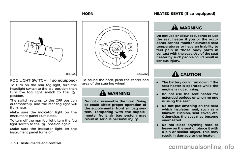
FOG LIGHT SWITCH (if so equipped)
To turn on the rear fog light, turn the
headlight switch to theposition, then
turn the fog light switch to the
position.
The switch returns to the OFF position
automatically, and the rear fog light will
illuminate.
Make sure the indicator light on the
instrument panel illuminates.
To turn off the rear fog light, turn the fog
light switch to the
position again.
Make sure the indicator light on the
instrument panel turns off.
SIC3982
To sound the horn, push the center pad
area of the steering wheel.
WARNING
Do not disassemble the horn. Doing
so could affect proper operation of
the supplemental front air bag sys-
tem. Tampering with the supple-
mental front air bag system may
result in serious personal injury.
WARNING
Do not use or allow occupants to use
the seat heater if you or the occu-
pants cannot monitor elevated seat
temperatures or have an inability to
feel pain in those body parts in
contact with the seat. Use of the seat
heater by such people could result in
serious injury.
CAUTION
. The battery could run down if the
seat heater is operated while the
engine is not running.
. Do not use the seat heater for
extended periods or when no one
is using the seat.
. Do not put anything on the seat
which insulates heat, such as a
blanket, cushion, seat cover, etc.
Otherwise, the seat may become
overheated.
. Do not place anything hard or
heavy on the seat or pierce it with
a pin or similar object. This may
result in damage to the heater.
HORN HEATED SEATS (if so equipped)
Page 111 of 453
.The climate controlled seat has
air filters. Do not operate the
climate controlled seat without
the air filters. This may result in
damage to the system.
. When cleaning the seat, never use
gasoline, thinner, or any similar
materials.
. If any malfunctions are found or
the climate controlled seat does
not operate, turn the switch off
and have the system checked. It
is recommended you visit a
NISSAN dealer for this service.
SSD1161
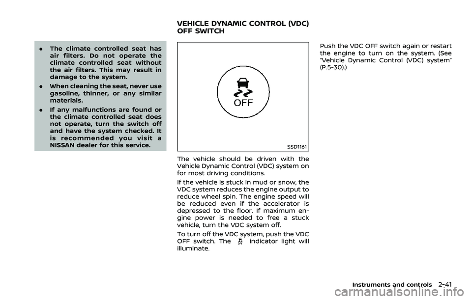
The vehicle should be driven with the
Vehicle Dynamic Control (VDC) system on
for most driving conditions.
If the vehicle is stuck in mud or snow, the
VDC system reduces the engine output to
reduce wheel spin. The engine speed will
be reduced even if the accelerator is
depressed to the floor. If maximum en-
gine power is needed to free a stuck
vehicle, turn the VDC system off.
To turn off the VDC system, push the VDC
OFF switch. The
indicator light will
illuminate. Push the VDC OFF switch again or restart
the engine to turn on the system. (See
“Vehicle Dynamic Control (VDC) system”
(P.5-30).)
Instruments and controls2-41
VEHICLE DYNAMIC CONTROL (VDC)
OFF SWITCH
Page 164 of 453
3-38Pre-driving checks and adjustments
WARNING
.Do not adjust the steering wheel
while driving. You could lose con-
trol of your vehicle and cause an
accident.
. Do not adjust the steering wheel
any closer to you than is neces-
sary for proper steering opera-
tion and comfort. The driver’s air
bag inflates with great force. If
you are unrestrained, leaning for-
ward, sitting sideways or out of
position in any way, you are at
greater risk of injury or death in a
crash. You may also receive ser-
ious or fatal injuries from the air
bag if you are up against it when
it inflates. Always sit back against
the seatback and as far away as
practical from the steering wheel.
Always use the seat belts.
SPA2583
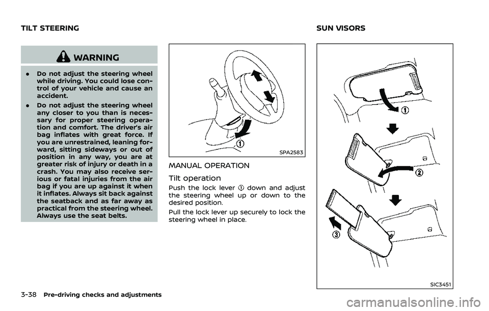
MANUAL OPERATION
Tilt operation
Push the lock leverdown and adjust
the steering wheel up or down to the
desired position.
Pull the lock lever up securely to lock the
steering wheel in place.
SIC3451
TILT STEERING SUN VISORS
Page 170 of 453

iPod® player operation (models with
navigation system) ............................................................. 4-68
Auxiliary input jacks (models with
navigation system) ............................................................. 4-70
CD/DVD/USB memory care and cleaning ....... 4-72
Steering-wheel-mounted controls
for audio ........................................................................\
.............. 4-73
Antenna ........................................................................\
............... 4-74
Car phone or CB radio ........................................................... 4-75
Bluetooth® hands-free phone system
(models with navigation system) .................................. 4-76 Regulatory information ................................................... 4-77
Voice commands ................................................................. 4-77
Control buttons ..................................................................... 4-78
Connecting procedure .................................................... 4-78
Phone selection ..................................................................... 4-79
Quick Dial ........................................................................\
........... 4-79
Making a call ........................................................................\
.... 4-82
Receiving a call ...................................................................... 4-82
During a call ........................................................................\
..... 4-83 Phone setting ....................................................................... 4-84
Troubleshooting guide ................................................. 4-85
Bluetooth® hands-free phone system (models
without navigation system) .............................................. 4-86
Regulatory information ................................................ 4-87
Using the system ............................................................... 4-88
Control buttons ................................................................. 4-90
Getting started ................................................................... 4-90
List of voice commands ............................................... 4-92
Speaker Adaptation (SA) mode .............................. 4-96
Troubleshooting guide ................................................. 4-98
NISSAN Voice Recognition System
(models with navigation system) .................................. 4-99 NISSAN voice recognition
Standard Mode .................................................................... 4-99
Using the system ............................................................. 4-102
NISSAN voice recognition Alternate
Command Mode ............................................................... 4-110
Using the system .............................................................. 4-119
Troubleshooting guide ............................................... 4-124
Page 175 of 453
SAA2143
MENU OPTIONS
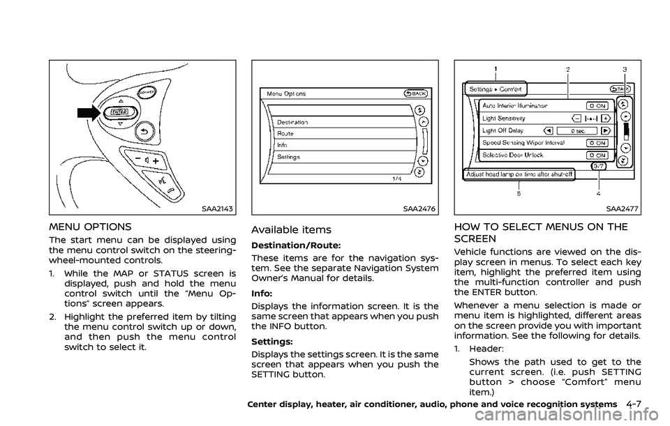
The start menu can be displayed using
the menu control switch on the steering-
wheel-mounted controls.
1. While the MAP or STATUS screen isdisplayed, push and hold the menu
control switch until the “Menu Op-
tions” screen appears.
2. Highlight the preferred item by tilting the menu control switch up or down,
and then push the menu control
switch to select it.
SAA2476
Available items
Destination/Route:
These items are for the navigation sys-
tem. See the separate Navigation System
Owner’s Manual for details.
Info:
Displays the information screen. It is the
same screen that appears when you push
the INFO button.
Settings:
Displays the settings screen. It is the same
screen that appears when you push the
SETTING button.
SAA2477
HOW TO SELECT MENUS ON THE
SCREEN
Vehicle functions are viewed on the dis-
play screen in menus. To select each key
item, highlight the preferred item using
the multi-function controller and push
the ENTER button.
Whenever a menu selection is made or
menu item is highlighted, different areas
on the screen provide you with important
information. See the following for details.
1. Header:
Shows the path used to get to the
current screen. (i.e. push SETTING
button > choose “Comfort” menu
item.)
Center display, heater, air conditioner, audio, phone and voice recognition systems4-7
Page 187 of 453
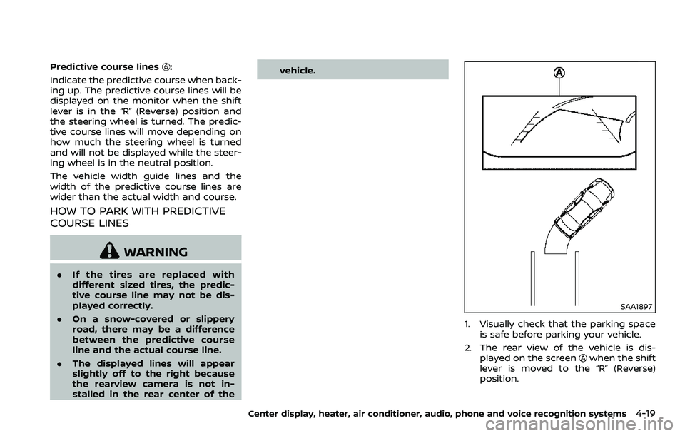
Predictive course lines:
Indicate the predictive course when back-
ing up. The predictive course lines will be
displayed on the monitor when the shift
lever is in the “R” (Reverse) position and
the steering wheel is turned. The predic-
tive course lines will move depending on
how much the steering wheel is turned
and will not be displayed while the steer-
ing wheel is in the neutral position.
The vehicle width guide lines and the
width of the predictive course lines are
wider than the actual width and course.
HOW TO PARK WITH PREDICTIVE
COURSE LINES
WARNING
. If the tires are replaced with
different sized tires, the predic-
tive course line may not be dis-
played correctly.
. On a snow-covered or slippery
road, there may be a difference
between the predictive course
line and the actual course line.
. The displayed lines will appear
slightly off to the right because
the rearview camera is not in-
stalled in the rear center of the vehicle.
SAA1897
1. Visually check that the parking space
is safe before parking your vehicle.
2. The rear view of the vehicle is dis- played on the screen
when the shift
lever is moved to the “R” (Reverse)
position.
Center display, heater, air conditioner, audio, phone and voice recognition systems4-19